
Lego PID — The Ultimate Line Follower
Algorithm for your EV3 PID Line Follower Robot — Episode#15
Hey everyone! in this LEGO’s episode, I’m going to teach you how to make the ultimate line follower for your EV3 robot: a PID line follower!
Jump to videos? to see my Lego’s youtube playlist — click here;)
A PID line follower is the most radical and complex type of line follower there is but it’s very rewarding because you’ll have the most sophisticated the most advanced the smoothest line follower you could possibly make and it’s definitely worth the effort because you’re going to have a flawless bulletproof line follower that’s very reliable and will work every time.
It’s the most refined and the fluid line follower you could possibly build.
I going to explain everything from the very beginning.
Let’s start by what is a PID control?
Proportional-Integral-Derivative (PID) control is the most common control algorithm used in industry and has been universally accepted in industrial control.What’s behind a PID Controller?
The basic idea behind a PID controller is to read a sensor, then compute the desired actuator output by calculating proportional, integral, and derivative responses and summing those three components to compute the output.An appliance using PID, for instance, an air conditioner inverter system can lower the energy consumption and increased temperature control for better thermal comfort compared to on/off controller. In this case, the PID control strategy is focused on low energy consumption and thermal comfort for the indoor user. Back to Lego, though…
Our purpose is to make Tribot follows a black line as fast as it can!
A Lego PID line follower has three parts to it; The first one is Proportional:
Proportional (P): simply multiplies the Error by the Proportional Gain (Kp) to get the controller output. In general, increasing the proportional gain will increase the speed of the control system response. However, if the proportional gain is too large, the process variable will begin to oscillate and your plant becames unsteady:/In dealing with Proportional, which is the P stands for, you will find a post sent by me in previous Lego’s Episode #12 where I’ve covered that, so maybe you might want to read this article before continuing to read this one.
The second part is Integral:
Integral (I): from school, turns out to be the area under the curve. The integral component sums the error term over time. The result is that even a small error term will cause the integral component to increase slowly. The integral response will continually increase over time unless the error is zero, so the effect is to drive the Steady-State-Error-To-Zero (2_SET_z).and the third part is the D that stands for Derivative:
Derivative (D): is just a mathematical term meaning rate-of-change. The derivative component causes the output to decrease if the process variable is increasing rapidly. The derivative response is proportional to the rate of change of the process variable. Increasing the derivative time - de(t) - parameter will cause the control system to react more strongly to changes in the error term and will increase the speed of the overall control system response.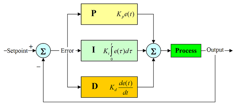
But don’t worry by now with all these concepts, and images… I’m going to explain to you what each of these three parts means individually and show you how we can translate this easily to your Lego Tribot v1.0:)
So to start it off, here is the general formula for a PID life:
PID = (target-value).kp+(integral+error).ki+(error-last_error).kdThis is the math function that we’re going to be incorporating into our program in order to make your EV3 Robot Follow The Line using a PID algorithm.
Now I know this math looks really scary right now and some of you might want to throw it up but I promise that this math is not nearly as difficult as it may seem at first and I’m going to breaking it down step by step to make each part of it more digestible.
However, before we actually jump right into building our Lego program, let’s understand by real example what PID really is like:
PID? Why would you mind?
Let’s say you’re inside this roller coaster \o/
Oops, it passes from the point (or better not even reached) where you would like to be, right?:(
Just for the sake of this example let’s assume that you would like to stop well at breakeven on the ground at roughly 100 us; This is your target, right?
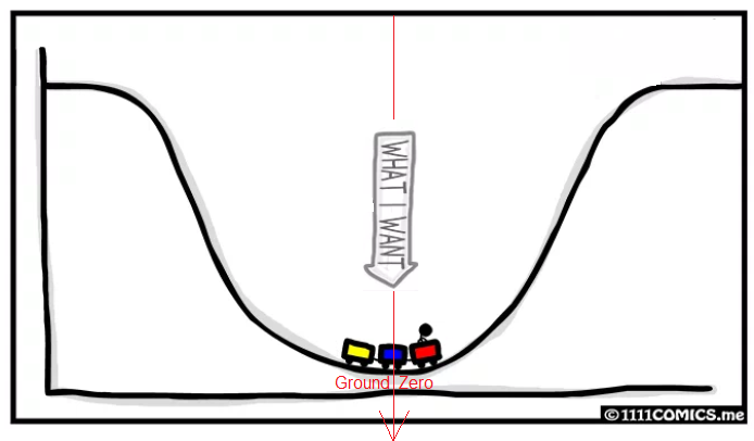
Here is what you need to do: First, obviously, implementing a braking mechanism; you will need to use the trolley brake and stop it, well, at break-even point ground zero, right? But, how?
It passes from the point initially, and gradually it finds the balance at the ground (zero on the graph above) like a pendulum… The shorter the time to reach the rest point the most perfect is your PID algorithm!
It seems to me that physically it is impossible to stop the trolley at the first turn. There is material stress limit, called by engineer Ultimate tensile strength (UTS), restriction of the human ability to withstand g-force, biologic and other system limitations…all right… we will stop the trolley as rapidly as we can, ok!?
Here is a graph animation trying to convey this idea of a pendulum(sorry for the imperfections…)
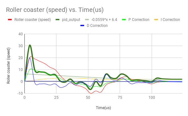
And here is a free graphics Roller coaster Speed x Time, which simulates mathematically the motion observed above; You can download the worksheet now to study PID with me!
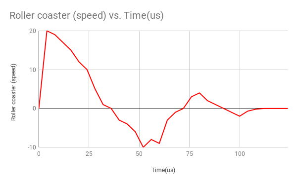
Please, see that the system gets an amazing speed in the first few seconds.
It is a huge linear acquisition, right?
Then the question is:
How much force should I apply to the brakes?
Let’s make an attempt here: hit hard the brakes, say, 50% proportional to the amount of the speed; This stands for Proportional correction proposal. See the green proportional line on the graph:
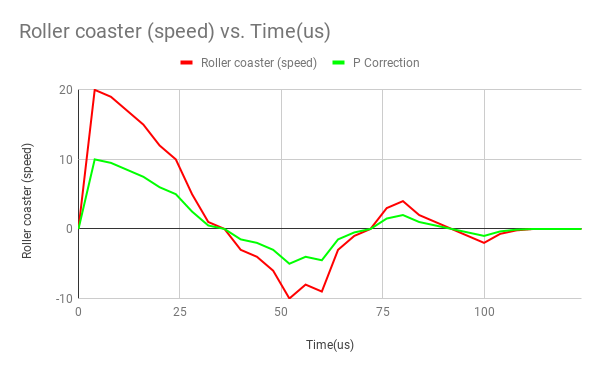
As soon as the errors occur as soon as the proportional correction is triggered.
Proportional cares for the present!
But wait! Take a close look at the graph above, my friend…Probably there is no time to make the correction…right at the start, the speed is tremendous!
Do we have how to anticipate this excessive speed gain or direction change?
Sure and the trick is the D; add the D part of the equation; the Derivative correction for the system follows; this makes an anticipate rection!
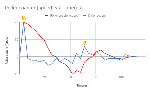
If you observe the behavior of the derivative blue curve you will see that it is greatly increased when the speed direction initializes or changes (focus on those two peaks depicted by the yellow arrows above).
In fact, the derivative calculates the rate of change of the variable, as said above, and appears on the curve thousandths of seconds before even the actual change of direction or speed, even before those changes become discernible by the system and that’s just what we need now \o/
Derivative cares for the future!
And finally let’s apply the Integral correction:
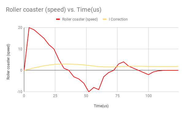
The integral simply make the sum of all values (errors, for the sake of this example) during the time lapse. See that the orange line is almost zero because the areas drawn by the curve tend to balance itself, but due to the friction, the original loop no longer repeats, hence the errors accumulate a little.
Integral cares for the past!
To understand, please calculate mentally the areas under the red curve and make the sum of them. If the graph were perfectly symmetric, based on the x-axis, the values would be equal and the integral (orange curve) would be zero. But we have factors that make the system lose momentum and these are frictions generated thought metal contacts and yet by the very movement of your body (mainly your neck) when subjected to such great changes of speed and directions (g-force); these minors error are treated by the integral equation.
Now adds all corrections curves together and you will have a mathematical function as a result (pid_output); and believe me, my friend…your problem is over! Your trolley will be at your command in just 100 us, right on the ground zero!
Congratulations, your PID is working \o/
I hope you understood the big picture of PID by now, although superficially, of course;)
ln short, PID it is an algorithm that controls a plant by using some system feedback and a given goal or set point, or target, whatever... This is all you need to understand by now:)
Let's jump right into performing our LEGO ultimate PID line follower robot algorithm!
Our Target
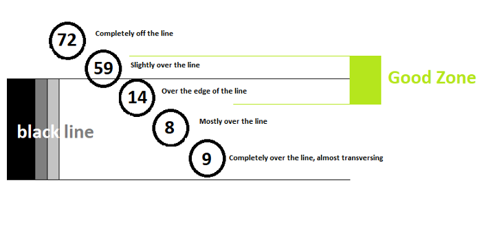
If we find the center point, we would have 72 + 8 divided by 2 would give us 40; let’s force a little more towards the black line and use the number 35, okay?
I’m going to say that 35 is the light sensor reading for our target. With this value, the Tribot must follow the Good Zone ideally.
P for Proportional
Proportional measures deviation from the target path that we’ve established here at 35.
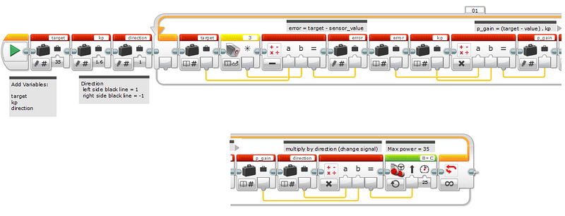
Proportional (kp)
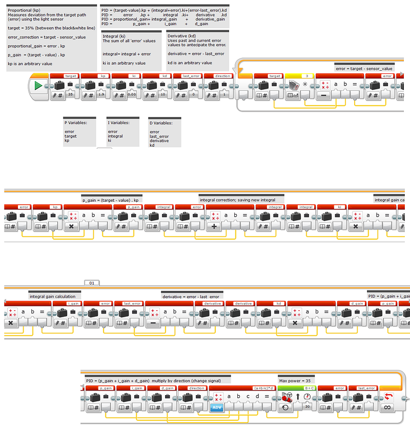
Measures deviation from the target path (error) using the light sensortarget = 35 (between the black&white line)error_correction = target - sensor_valueproportional_gain = error . kpp_gain = (target - value) . kpkp is an arbitrary valueTranslation to Lego’s G-EV3:
PI for Proportional & Integral
Integral (ki)
The sum of all 'error' valuesintegral= integral + errorki is an arbitrary valueTranslation to Lego’s G-EV3:
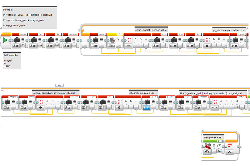
PID for Proportional & Integral & Derivative
PID = (target-value).kp + (integral+error).ki+(error-last_error).kdPID = error.kp + integral.ki + derivative.kdPID = proportional_gain + integral_gain + derivative_gainPID = p_gain + i_gain + d_gainTranslation to Lego’s G-EV3:
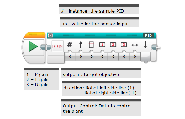
My Block PID
More PID Theory
Thank God we have a PID technology!
Let's see what is the term closed loop, that you may find in the literature:
Closed Loop Control System (CLCS) is the process of reading sensors to provide constant feedback and calculating the desired actuator output is repeated continuously and at a fixed loop rate .Our goal is to tune a PID controller to reduce overshoot in reference tracking or to improve rejection of a disturbance at the plant input.
What is disturbance rejection? From MacMynowski:
The term disturbance rejection was used a number of times in lecture today to describe the purpose of feedback. With feedback, the controller is able to use the output to shape the input of the system.And how about Nonlinear System:
Nonlinear System (NLS) is a system in which the control parameters that produce a desired response at one operating point might not produce a satisfactory response at another operating point.I read that simulation is an important tool for getting PID right.
I already did this in the previous post.
The Setpoint (SP) is the value that we want the process to be.
The PID controller looks at the setpoint and compares it with the actual value of the Process Variable (PV).
Modes of Control
There are various modes out there, here are some combinations:
P — Sometimes used
PI — Most often used
PID — Sometimes used
PD — rare as hen’s teeth but can be useful for controlling servo motors.
Under The Hood Of The PID Controller — Tuning
The process of setting the optimal gains for P, I and D to get an ideal response from a control system is called tuning.
The gains of a PID controller can be obtained by trial and error method. This is my approach to the solution.
I started with PI. This way is the most common occurrences in the literature.
The tricky thing about Integral Action is that it will really screw up your process unless you know exactly how much Integral action to apply.
The way to adjust how much Integral Action you have is by adjusting a term called minutes per repeat.
So where does this strange name come from? It is a measure of how long it will take for the Integral Action to match the Proportional Action.
In other words, if the output of the proportional box on the diagram above is 20%, the repeat time is the time it will take for the output of the Integral box to get to 20% too.
Derivative action improves the controller action because it predicts what is yet to happen. Of course, you can try and filter the noise out, but my advice is that, unless PI control is really slow, don’t worry about switching D on.
Another Tunning Method:
The Ziegler-Nichols method is another popular method of tuning a PID controller. It is very similar to the trial and error method wherein I and D are set to zero and P is increased until the loop starts to oscillate. Once oscillation starts, the critical gain Kc and the period of oscillations Pc are noted. The P, I and D are then adjusted in a tabular column.
And that’s all, folks!
Thanks for reading my episode this week; if you found it helpful be sure to subscribe for more tutorials and if you like this share with your friend.
And if you have an idea for a tutorial be sure to submit it in the comment section below.
Thank you and I’ll see you next time. bye o/
Download All Files For This Project
Related Posts:
23° ArduSeries — PID sample for Arduino — HowTo Control devices with PIDLibrary
5/5 Part JayThree Balancing Car Project — PID without a PhD
01º Lego Episode — Our Startup’s Journey — Invaders and Invasions?
02º Lego Episode — Timmyton — Lego-Learning-By-Playing — L2BP Series
04º Lego Episode — Lego Motions — Tribot v 1.0 — Seeing Your Creation Move — Move Steering Block
05º Lego Episode — Lego Motions — Move Tribot Around — And Backward…Five Programs Files
06º Lego Episode — Lego Sensors — Touch N Color — Two out of five human senses — Touch N Sight
07º Lego Episode — Lego Sensor — LineFollower — Line Follower Tribot v1.0
08º Lego Episode — Maze Solving Robot v1 — Lego Solution Right-Wall-Follower-Robot
09° Lego Episode — Gettle_&_Sound_Bots — How gentle can a robot be? What is the audible range of the human ear? How deep can we dive?
10° Lego Episode — Data Logging — Data Collection and the EV3
11º Lego Episode — Binning the LineFollower Code — Binning: Arithmetic To Map Sensor Reading
12º Lego Episode — A Proportional LineFollower Robot — Advanced Math To Improve Your Robot’s Steering
8th KidSeries — J3 Follower Line Robot v1.0 — The Simplest Follower Line Robot
13º LEGO Theory — Multitasking — A very Useful Programming Technique
14º LEGO formula — Normalizing Data — Converting Data to Use The Same Range
15 º Lego Episode — PID — The Ultimate Line Follower — Algorithm for your EV3 PID Line Follower Robot
16° Lego Meets Pixy Episode — How to Connect Your Inexpensive Camera Module to Lego
18° Lego Episode — GEARS & WORMS — Geartrains & Worm & Clutch Gears
23° Lego Episode — Differential Explained — How Differential Works?
24° Lego Episode — PitBot — A Star Is Born — Working at The First Structure in Our Sparring Robot
25° Lego Episode — PitBot Is Agressive? Well, No Worries! — Making PitBot bite!
26° Lego Episode — Dancing Good w/ PitBot — All The Secret for Replicate This Awesome Robot
27 ° LEGO Episode — Sumo Arena is Ready! — Here is the playing arena for Arduino x Lego
28 ° LEGO Episode — Pick Pitbot Up! — Our Robot Are Leaving Body & Paint Shop
28 ° LEGO — B — Episode — Pitbot Battery & Sensor Setup — Preparing The infrastructure for running Arduino code
29 ° LEGO Episode — Bridging All Sensors Together — Pitbot — Collecting All Codes for the Final Act of Giving Behaviors to Robot
Credits & References
Book: The Art of Lego Mindstorms EV3 Programming by Terry Griffin
Building Smart LEGO MINDSTORMS EV3 Robots by Kyle Markland (thank you, dude:)
EV3 Large and NXT Motors — The Differences Explained
Building Instructions & Program Descriptions
LEGO® 9V Technic Motors compared characteristics


