
JayThree Balancing Car Project — Part 4/5
J3BC Circuit Board Prototyping Tips and Tricks (with Slides)
The goal of this thread is to make a quick Through-Hole Soldering Guide (THSG). You’d come out with a prototype ready and working! ...and more, let's rehearse the PID in this context and see some Arduino interruption code. All concepts converge on our ultimate goal: J3BC project!much hurry? Part 5/5!
We will test four Arduino’s codes (see my Github repo, plz!):
35_ProMini_Two_StepperMotor_13.ino — → Code to test the two stepper motor for J3BC project.
_35_ProMini_Stepper_Interruptions_14 — →simple code using ISR interruption service routine.
_35_stepper_back_forward_16.ino — → Here we tested the engine forwards and backwards. Very basic!
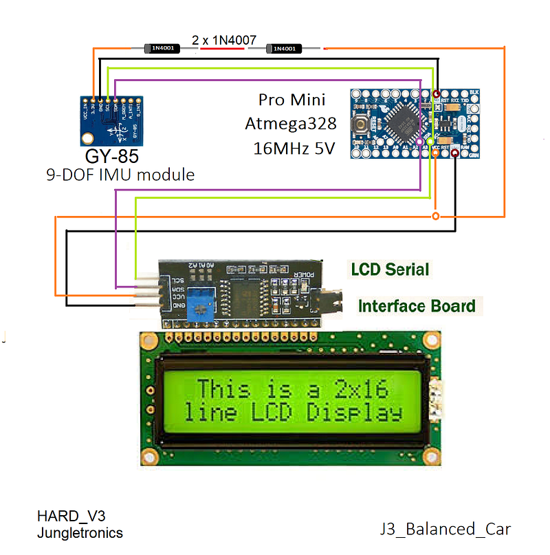
_35_J3_GY85_IMU_15.ino — → This code is used to establish or verify angles in some plane. This code is very long and sophisticated and was largely based and recompiled from this page http://www.brokking.net/imu.html code for migration of the IMU GY-521 board to the GY-85 board. It’s an initial version. We accept collaborations:D Try it yourself! See schematic below!
Notes for this test:
- I first tested the code on Arduino ONE;
- My Arduino IDE is installed manually in the C directory → C: \ arduino;
- Then I downloaded the zip of the library by Francisco Malpartida New LiquidCrystal on https://bitbucket.org/fmalpartida/new-liquidcrystal/downloads/;
- Unzip and extract it to the directory C:\ arduino \ libraries \ NewliquidCrystal;
- I uploaded this code for Arduino Pro mini code: _35_HelloWorld_LCD_i2c_Anime_Bubbles_15;
- Board: Arduino Pro or Pro Mini
- Processor: ATmega328 (5v, 16 MHz)
- Port: COM3 (see yours on Win > Device Manager > Port (COM & LPT));
- Programmer: Any, I use Arduino As ISP;
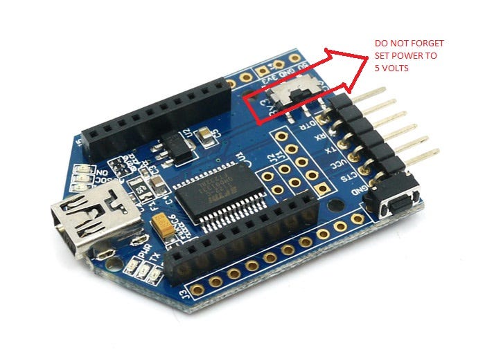
- Do not forget to power the LCD with 5v. Otherwise nothing will appear on the screen!
- I pay close attention to the connections A5 →SCL and A4 → SDA of the I2C bus;
- Finally upload _35_J3_GY85_IMU_15.ino and you’re done!
THAT’S IT! have fun with the angles! If you will see this video…
Board Soldering
The pitfalls of working with soldering are numerous.
I installed the PRT-00115 Headers Female to hold all the components and make it possible to reuse each of them. My Bonus Feature is to protect the components against high temperatures during soldering procedures.
The biggest difficulty that I faced was to draw the connections on the other side of the board, inverted, upside down…
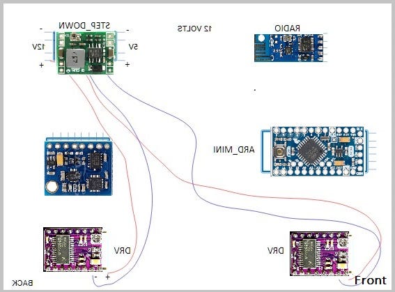
I have found that you can draw all the components and connections in a convas and then rotate the drawing by inverting the image horizontally. It’s a really cool trick!... easy and fast…Here’s the images (wiring), use the back one!
From now on, I summarize the tasks necessary for build your own prototype. Follow the steps in this same sequence and you will succeed \o/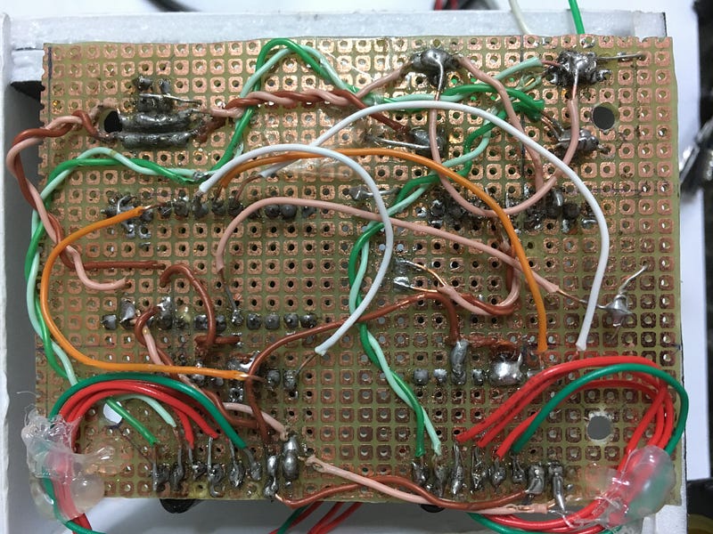
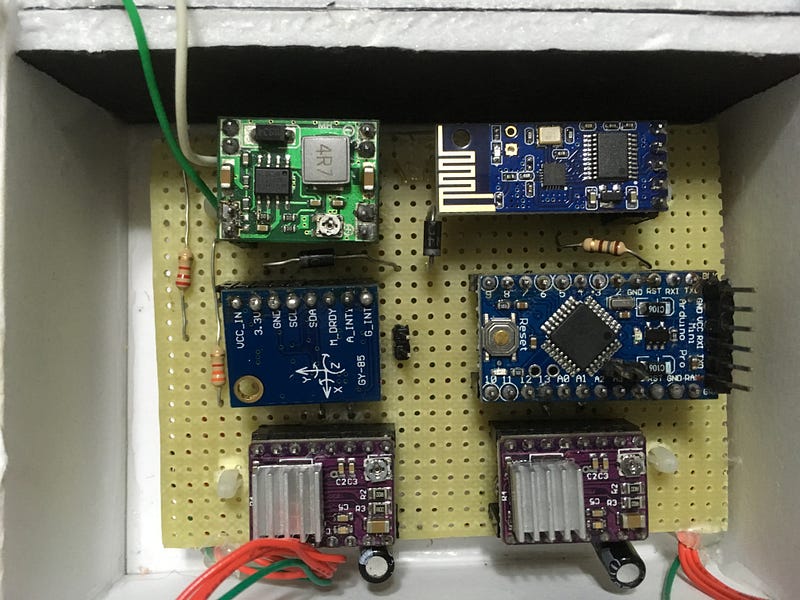
This is the face on which its components are on the reverse side (I confess that I do not have much skill with soldering…but it is working; I already bought the GY-521 and I intend to make version 2. The card is portable as well as the components. Cool, right?) Therefore, this is the Circuit Board Prototype plate. The components are mirrored (advance the slides according to your evolution in the soldering)
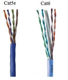
I peeled an RJ-45 (CAT5e or Cat6) internet cable and used the resulting wires. It is semi-rigid facilitating the work.
Separate functionalities by different colors.
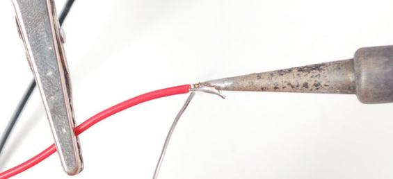
Always put some tin on the ends of the wires. It works well, try it!
The first wiring went to the 12-volt bus. The wiring used is light green to negative and dark green to positive. See photo. Choose freely though…
Now, you can use these inverted images to do the soldering procedure step by step. Once you have done the soldering you can check the connections with the front images. Simply place the multimeter in the continuation range and examine track by track. See image/wiring directory.
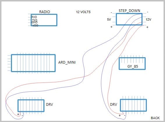
Use two capacitors of 100 microfarads. they serve to avoid power surges in the circuit.
Now the wiring to 5 volts. follow the sequence. It must be done with care.
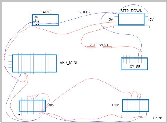
I used the brown tone wiring for 5v mark.
Notice that we have two diodes (1N4001) to lower the voltage to approximate 3v3 for the GY-85 board. The GND is common for both bus (12 and 5 v).
I wired the threads in pairs for better organization of chaos (is it possible?).
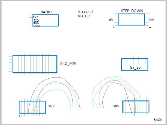
Now let’s take care of the motor connections. I used the motor’s own cable and glued its end for strain relief.
Now let’s go to the battery monitor. It’s very simple but functional:
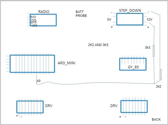
I used R1= 2k2 and 3k3 resistors:
Calculation: R1 + R2/R1
2200 + 3300 / 2200 = 2.5
2.5 * 5v = 12.5V (Battery supply voltage)
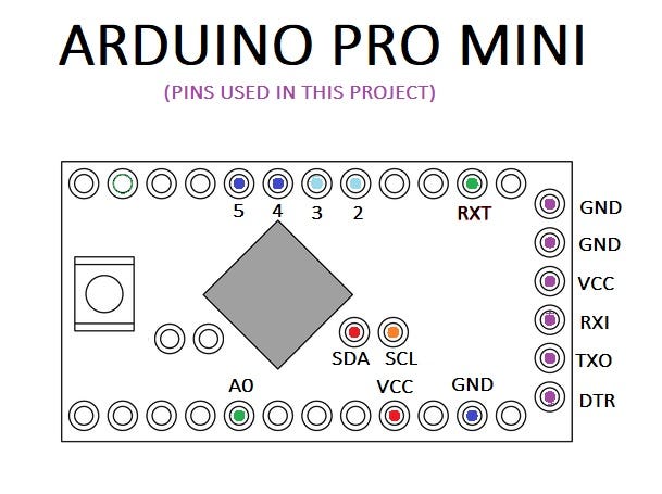
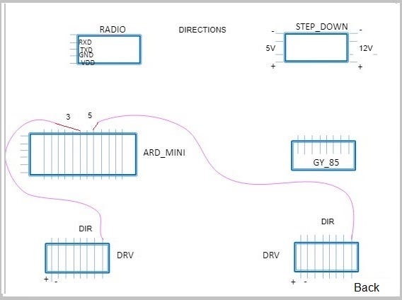
The next one deals with the arduino pins that will take care of the step motor direction:
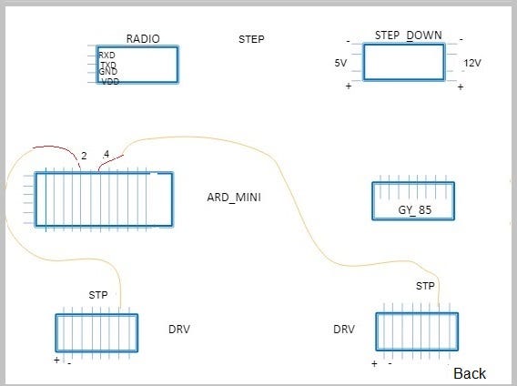
..and another one for the steps …
Motor_Left: Dir 3 & STP 2;
Motor_Right: Dir 5 & STP 4;
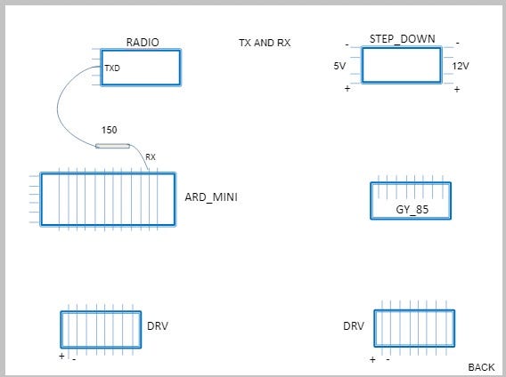
And finally we take care of the radio transmission for the Arduino Mini. Only the TXD_Radio to RX_Arduino Mini connection.
Circuit is ready :) Woohoo!!!
If you follow these steps you will have a functional prototype =) for sure!
For your references here are some back image:
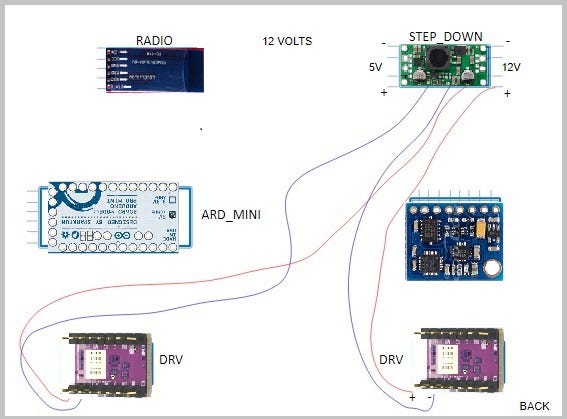
Which you can inverting the image horizontally and you will end up with the front of the board shown below:
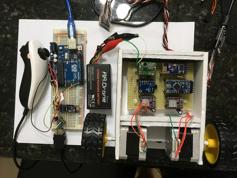
I’ve tested all the codes for J3BCP and everythings is alright! Check it out!
Now that we’re done with the board and everything is working let’s use Insulation Colorless Spray to prevent rust and poor contact…in fact, I used plastic glue for that purpose. Anyway, remains the tip:-)
There you have it!
Logically a printed circuit board would be the best of all worlds. Soldering in these modes shown here is an arduous and error-prone task that can invalidate all work:( Oh, oh no, oh no, oh no…
Better PCBs in Eagle it’s a good start.
So always be patient! Do not wait the project to end on the its first day. It won’t! It’s the kind of project you have to sleep on it, as Jeremy Blum would say in his Idea to Innovation Flowchart:)
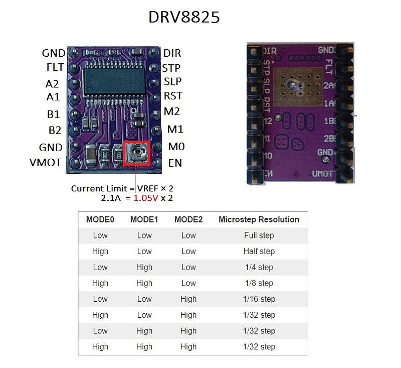
DRV8825 Active Current Limmiting
My Motor is: 12V NEMA 17 Stepper Motor JK42HS34–0424A.
The DRV8825 supports active current limiting.
One way to set the current limit is to use trimpot to adjust output current.
Set the current limit is to measure the voltage on the REF trimpot which values are related by this formula:
Current Limit = VREF x 2As the measured current must be 0.7 times the current limit and the DRV8825 driver IC has a maximum current rating of 2.5 A per coil, but the current sense resistors further limit the maximum current to roughly 2.1A , so the above equation is solved like this:
2.1 A = VREF x 2 -> VREF = 1.05 VSo make 1.05 v appear on the trimpot and the stepper motor will work correctly (use a multimeter by doing a GND on the battery and visualizing the voltage of the trimpot). That’s how I did it!
Interruptions Issues
The motor in the final version will be triggered via interruption. The idea is to generate an interrupt every 20 milliseconds and control the motor. Here is the required code.
void setup() { TCCR2A = 0;
TCCR2B = 2;
TIMSK2 = 1 << TOIE2;
TCNT2 = 0xD9;
}void loop() {
}ISR(TIMER2_OVF_vect) {(...)}
That’s a basic structure of a interruptions on arduino.
Calculation for JayThree Balancing Car Project:Overflow = Counter * Prescale * Main Frequency
Overflow = 39 * 8 * 1/16M
Overflow = 0.0000195 sec or ~ 20 usI’ll will talk about this issue in the future post. The code above is functional though :)
Please see datasheet for details: http://www.atmel.com/Images/Atmel-42735-8-bit-AVR-Microcontroller-ATmega328-328P_Datasheet.pdf
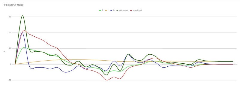
PID Rehearsals
In this worksheet we simulate a robot that balances itself. Notice that the output of the gyroscope behaves like a pendulum. It passes from the point initially, and gradually finds the ideal stop angle.
I used these formulas in this spreadsheet:
P (PROPORTIONAL) - Present TenseFormula:P = error * P_gainI (INTEGRAL) - Past Tense
Formula:I = sum of errors * I_gainD (DERIVATIVE) - Future Tense
Formula:D = Diff between current - previous errors * D_gainObservation: at the moment the error is finally cleared, the value of the final result equals the value of the integral. The values P and D end in zero, except the I.
The pid_output is then saved and represents the information we need to balance the system.
See the PID_OUTPUT graph that aggregates all the results and emphasizes the final result.
We already have all the necessary codes and knowledge...
Now let’s finalize the project. I Hope so…
Until the next post, bye!
Cheers!
Download All Files From Google Drive
Part 1 — — Part 2 — — Part3 — Part 4 — -Part5
References:
Your Arduino Balancing Robot (YABR)-by J. Brokking
❤︎² Derivatives… What? (mathbff)-by Nancy
PID Control — A brief introduction — by Brian Douglas
Simple Examples of PID Control — by Brian Douglas
What PIDs do and how they do it — by RCModelReviews
Published on Oct 03, 2017