
L298N: Dual Full-Bridge Driver
Darlington Transistor Arrays Based — 3A@50v peak — Ardu-Serie#52
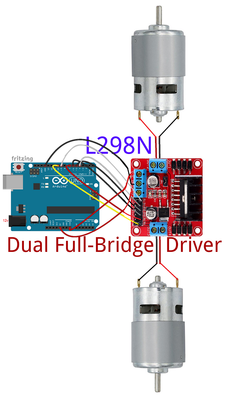
Goal: run two 12v 350 RPM motors on one L298N Driver. These motors are part of my project Meet J3C3 — Assembly Techniques — J3 Caterpillar-Crawler-Chassis v 1.0 — ArduSerie#46
The L298 is a high voltage, high current dual full-bridge driver designed to accept standard TTL logic levels and drive inductive loads such as relays, solenoids, DC and stepping motors.
Two enable inputs are provided to enable or disable the device independently of the input signals.
The emitters of the lower transistors of each bridge are connected together and the corresponding external terminal can be used for the connection of an external sensing resistor. An additional supply input is provided so that the logic works at a lower voltage.
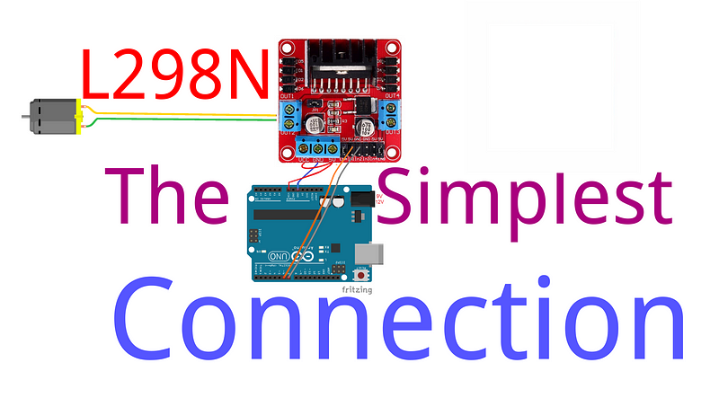
Here is my first attempt:
And here is my second Attempt:
The Only Consideration About This Module
The great concern of this module has a relation with the 5v jumper (JP1). If you use motors below 12v, keep the jumper and 5v will be output and the internal circuits will be fed by the 5v regulator. That was my approach to the primary lab above:)
If you use motors above 12v, remove the jumper; with that, you disable the 5v regulator, the corresponding pin will be input and you need to feed the internal circuit with 5v. That was my approach to the secondary lab below;)
That’s it!
Thanks for you guys for reading/watching. Hit the like button if you like the post/videos. Subscribe to the channel to get notified when I put out new videos and
I’ll see you again next time:)
Bye!
Download All Files for This Project
— published at Oct 2018 —
Related Posts:
Meet DoRobot — Assembly Techniques J3 Caterpillar-Crawler-Chassis v 1.0 — ArduSerie#46
EASYDRIVER: 4-Wire-Stepper Motor Driver — Brian Schmalz Design on A3967 IC — Bi-Polar Motors — .75A@30v peak — Making Using These a Breeze! Ardu_Serie#48
DRV8825 — High Current Stepper Motor Driver Carrier — Stepper Motor — Bipolar Mode — 2.5A@45v peak — Ardu_Serie #59
L298N — Dual Full-Bridge Driver — Darlington Transistor Arrays Based — 3A@50v peak — Ardu-Serie#52
TB6612FNG: Dual DC Motor Driver — SparkFun Motor Driver — [email protected] peak — Ardu-Serie#49
A4988 — Stepper Motor Driver Carrier — Allegro’s A4988 — Bipolar Stepper Motor Driver — 2A@35v peak — Ardu-Serie#53
Adafruit Motor Shield v1 & v2–4 DC Motors or 2 Stepper Motor or 2 Servos — 1.2A@25v & 3.2A@15v peak — Ardu-Serie#54
IFR 520 MOS — Module + DoRobot — Switch Heavy DC Loads — 10A@100v peak — Ardu-Serie#60
L9110 H-bridge module + DoRobot — DC Stepper Motor Driver Board — .8A@12 v peak — Ardu_Serie#62
BTS7960B- High Current PN Half Bridge — High Current Motor Drive Applications — NovalithIC T M — 43A@24v peak — ArduSerie#64
VNH2SP30 — Monster Moto Shield — Use This Board In Extreme High-Demand Application — Full-Bridge Motor Drivers — 30A@16v peak — 30 Ardu_Serie#63