
DRV8825: High Current Stepper Motor Driver Carrier
Stepper Motor — Bipolar Mode — 2.5A@45v peak — Ardu_Serie #59
Hi, this is a higher-performance drop-in replacement for A4988 stepper motor driver carriers boards in many applications.
Simple to use and it is quite robust. I used this driver in my car balance project.
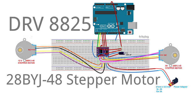
I’ll test it on two 5 and 12 v stepper motors:
The Code
What you’ll need:
1 x Arduino Uno
1 x DRV8825 Driver
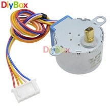
1 x 24BYJ48 5 v Stepper Motor
1 x breadboard
1 x 24BYJ48 12 v Stepper Motor
1 x 100uF capacitor
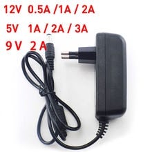
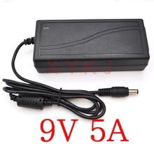
1 x Font Wall 12 v (.5A) and 5 v (.5A)
* x Jumper Wires
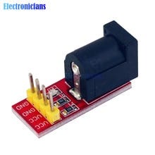
1 x 2.1mm x 5.5mm Power Adapter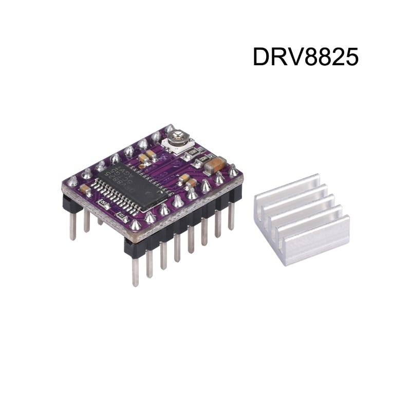
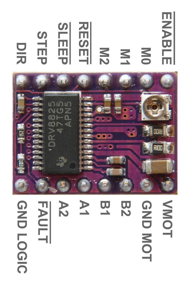
DRV8825 — An Integrated Motor Driver Solution For Bipolar Stepper Motors
The Characteristics
It goes natively 1/32 at the same jumper settings the A4988 runs 1/16, which directly translates into a more silent running (potentially);
It also has a heck of a lot of amperage headroom;
The device (DRV8825) integrates:
i) two NMOS H-bridges
ii) current sense
iii) regulation circuitry
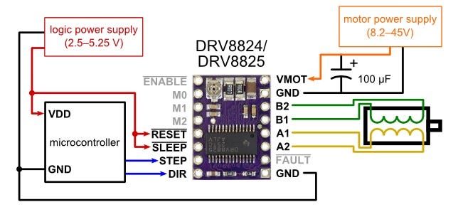
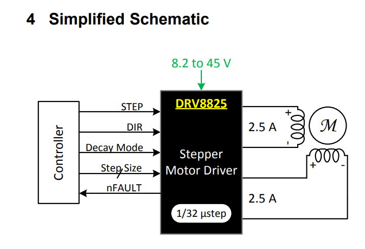
iv) a microstepping indexerPowered with a supply voltage between 8.2 and 45 V;
Capable of providing an output current up to 2.5 A full-scale;
A simple STEP/DIR interface allows for easy interfacing to the controller circuit;
The internal indexer is able to execute high-accuracy micro stepping without requiring the processor to control the current level;
The current regulation is highly configurable;
Three decay modes of operation: fast, slow, and mixed decay;
Low-power sleep mode is included which allows the system to save power when not driving the motor;
Suitable for two-phase and four-wire stepper motor;
Input Voltage:8.2–45V DC (Just power the stepper motor driver), 1.6A output current per coil;
For instance, driving a motor in quarter-step mode will give the 200-step-per-revolution motor 800 micro-steps per revolution by using four different current levels.
The resolution (step size) selector inputs (MODE0, MODE1, and MODE2) enable selection from the six-step resolutions according to the table below. All three selector inputs have internal 100kO pull-down resistors, so leaving these three micro step selection pins disconnected results in full-step mode. For the microstrip modes to function correctly, the current limit must be set low enough so that current limiting gets engaged. Otherwise, the intermediate current levels will not be correctly maintained, and the motor will skip micro-steps.
Built-in indexer logic in the DRV8825 allows a number of different stepping configurations. The MODE0 through MODE2 pins are used to configure the stepping format as shown in Table 1.
Table 1. Stepping Format
MODE0 MODE1 MODE2  Microstep Resolution
Low   Low   Low    Full step
High  Low   Low    Half step
Low   High  Low    1/4 step
High  High  Low    1/8 step
Low   Low   High   1/16 step
High  Low   High   1/32 step
Low   High  High   1/32 step
High  High  High   1/32 step
Control inputs
Each pulse to the STEP input corresponds to one micro-step of the stepper motor in the direction selected by the DIR pin. These inputs are both pulled low by default through internal 100k pull-down resistors. If you just want rotation in a single direction, you can leave DIR disconnected.
The chip has three different inputs for controlling its power states: RESET, SLEEP, and ENBL. For details about these power states, see the datasheet. Please note that the driver pulls the SLEEP pin low through an internal 1MO pull-down resistor, and it pulls the RESET and ENBL pins low through internal 100k pull-down resistors. These default RESET and SLEEP states are ones that prevent the driver from operating; both of these pins must be high to enable the driver (they can be connected directly to a logic “high” voltage between 2.2 and 5.25 V, or they can be dynamically controlled via connections to digital outputs of an MCU). The default state of the ENBL pin is to enable the driver, so this pin can be left disconnected.
Note: The coil current can be very different from the power supply current, so you should not use the current measured at the power supply to set the current limit. The appropriate place to put your current meter is in series with one of your stepper motor coils.
Here is the video:
Power Dissipation Considerations
The DRV8825 driver IC has a maximum current rating of 2.5 A per coil,
This product can get hot enough to burn you long before the chip overheats. Take care when handling this product and other components connected to it.
For my car balance project I’ve got a NEMA 17, rated at 0.3 Amps, stepping angle of 1.8 degrees;
I hope this helps anyone else who may have the same stepper motor driver.
Just wanted to say thanks to being with us! bye!
Download All File For This Project
References & Credits:
DRV8825 Stepper Motor Driver Carrier, High Current
Arduino Stepper Drivers Tutorial-2/2 by R Jordan Kreindler in Arduino
Stepper Motor Basics — 5 Wires Unipolar / Bipolar Motor
Stepper Motor Basics — 4 Wires Bipolar Motor
— published at Oct 2018 —
Related Posts:
Meet DoRobot — Assembly Techniques J3 Caterpillar-Crawler-Chassis v 1.0 — ArduSerie#46
EASYDRIVER: 4-Wire-Stepper Motor Driver — Brian Schmalz Design on A3967 IC — Bi-Polar Motors — .75A@30v peak — Making Using These a Breeze! Ardu_Serie#48
DRV8825 — High Current Stepper Motor Driver Carrier — Stepper Motor — Bipolar Mode — 2.5A@45v peak — Ardu_Serie #59
L298N — Dual Full-Bridge Driver — Darlington Transistor Arrays Based — 3A@50v peak — Ardu-Serie#52
TB6612FNG: Dual DC Motor Driver — SparkFun Motor Driver — [email protected] peak — Ardu-Serie#49
A4988 — Stepper Motor Driver Carrier — Allegro’s A4988 — Bipolar Stepper Motor Driver — 2A@35v peak — Ardu-Serie#53
Adafruit Motor Shield v1 & v2–4 DC Motors or 2 Stepper Motor or 2 Servos — 1.2A@25v & 3.2A@15v peak — Ardu-Serie#54
IFR 520 MOS — Module + DoRobot — Switch Heavy DC Loads — 10A@100v peak — Ardu-Serie#60
L9110 H-bridge module + DoRobot — DC Stepper Motor Driver Board — .8A@12 v peak — Ardu_Serie#62
BTS7960B- High Current PN Half Bridge — High Current Motor Drive Applications — NovalithIC T M — 43A@24v peak — ArduSerie#64
VNH2SP30 — Monster Moto Shield — Use This Board In Extreme High-Demand Application — Full-Bridge Motor Drivers — 30A@16v peak — 30 Ardu_Serie#63