
Compare Mode w/ Atmel Studio 7 & UNO (Episode#07)
If we look at the CCP Module we have Capture (as Input) allows us to measure the time between two events; Compare (as Output) allows the generation of a signal on the CCPx pin at predefined time intervals: it is useful if we want to generate a programmable width pulse on the pin (example control a drone) and lastly PWM (output) generation of a pulsed square wave signal with ON and OFF cycle width control (10-bit resolution). Well in the previous episodes we saw the common mode via Timer1 interrupt; now we will enter the CCP module for good! In this post we’ll cover COMPARE! welcome!
Step#01→ As usual in this serie Copy/Paste the previous code to a new project on Atmel Studio 7. Good!
In order to change the nomal mode to compare mode look at data sheet page 132 upward; Table 16–4. Waveform Generation Mode Bit Description.
All we need to set is the bit WGM12 that is on TCCR1B byte:
TCCR1B |= (1 << CS12) | (1 << WGM12);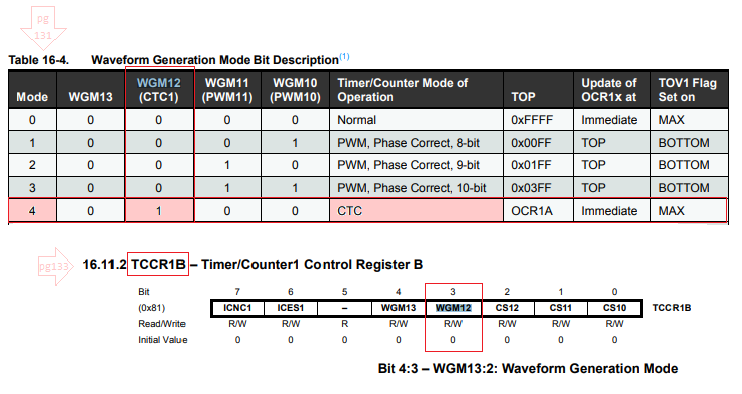
Step#02→ If you look again the main caracteristics of Atmega ATmega/328/P you’ll understand there are two channel on Compare outputs on OCxA and OCxB. [more detail see my post about ATtiny85].
We should also change the kind of interruption we need. We had the Overflow Timer1 Interrupt and we will switch to Output Compare on Channel 1. Now here’s a new technique in Atmel Studio 7; Follow this tip with me! Place the cursor over the TOIE1 in:
TIMSK1 |= (1 << TOIE1);Alt + G and you’ll be redirected for iom328p.h. Right below copy OCIE1A and past in the code above n’you’ll get:
TIMSK1 |= (1 << OCIE1A);Step#03 → Use the same technique to find the Compare vector A; Place the cursor inside TIMER1_OVF_vect:
ISR(TIMER1_COMPA_vect)
{
  LedToggle;
}Step#04 → Now the function representing the frequency we wanted to overflow at:
void Timer_Frequency(uint8_t freq)
{}Step#05 → Transfer this part from Main inside this brand new function:
void Timer_Frequency(uint8_t freq)
{
TCCR1B |=   (1 << CS12) | (1 << WGM12);
TIMSK1 |= (1 << OCIE1A);
}
You can clear the code up! Good!
Step#06→ Rearrage the formula found on page 123 and you’ll get:
OCRnA = (F_CPU/(Frequency * 2 * N) - 1)OCRnA — Output Compare pin we want to set it’s frequency;
F_CPU — our Arduino 16MHz cycle;
N — Prescale used (246)
And put this right in our code make we remember what we’ll need to do ;-)
Step#07 → substitute the real values in the formula and…
OCR1A = (F_CPU/(freq * 2 * 256) - 1);Step#08 → And finally make a call to this methods in main:
int main(void)
{
  Timer_Frequency(10);
...
}Step#09 → There you have it!
Just F7, and Sendo To Arduino UNO.
Code?
https://github.com/giljr/avr/tree/master/atmel
There you have it!
Look for Episode #7:-)
In the next post we will use AVRs timers to generate some PWM!
Take care!See you soon!
References & Credits
Follow along with the entire ‘Getting Started with AVR’ series: http://bit.ly/GettingStartedwithAVR
→Goto Episode#08
Complete Serie:
#00 HowTo-Load-Into-Arduino-AS7
#07_Compare Mode
#08
#09
#10