Building an 8-bit computer in Logisim (Part 4 — Status Flags)
This is the forth article in a series. If you haven’t read the previous parts, you can find them here:
Now that we have our main arithmetic sorted, in this part, we will be looking at how to build the Arithmetic Logic Unit (ALU).
What are status flags?
Status flags are usually a single bit that tells us some information about the last arithmetic operations that we did. So a flag is either set to 1 (true) or 0 (false). Four common flags are:
- Carry Flag (C)
- Zero Flag (Z)
- Negative/Signed Flag (N)
- Overflow/Underflow Flag (V)
Let’s take a look at each flag in more detail.
Carry Flag (C)
The carry flag is set to 1 (true) if the arithmetic operation results in an output carry bit of 1. An example of this would be if we try and add 255 + 255. In binary 255 is 1111 1111. Notice that we are dealing with an unsigned 8-bit number here. Let’s set both A and B to 1111 1111 on the ALU.
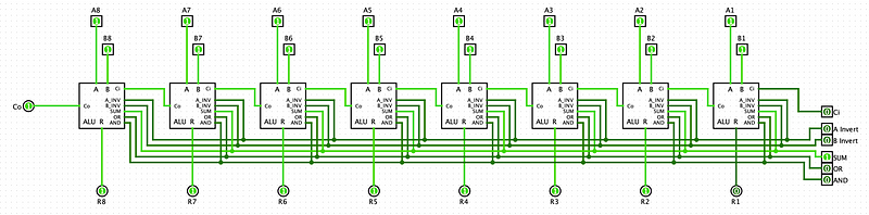
The output of the ALU is 1111 1110 (254 decimal). This is obviously not the right answer. So what happened here? Well, the operation produced an output carry. If you recall from previous parts, the output carry is used so that we can chain multiple full adder circuits together. But if the last full adder in the chain produces an output carry bit, it has nowhere to feed into. As you can see from the image above, that is precisely what happened here. The output carry of the last ALU block is set to 1. This tells us that the actual result of our operation should be 1 1111 1110 (510 decimal).
In a sense, the carry flag, which is just the carry output of the last ALU block, tells us the 8-bit result of the operation is not the whole result. Later, when we end up programming our computer, we can use this information to make conditional jumps. It is important to note that the carry flag is only meaningful if we are dealing with unsigned arithmetic operations. For logical operations like AND and OR, and signed arithmetic operations, we can generally ignore the carry flag.
Zero Flag (Z)
The zero flag is set to 1 (true) if the result from our arithmetic operation is equal to zero. For example 5 − 5 = 0 or 8 × 0 = 0. Let’s take a look at an example using our basic ALU circuit that we built in the previous section.
We will try to use the circuit to calculate 7 − 7. As an 8-bit binary number, 7 is 0000 0111. So we set A and B on the ALU both to 0000 0111. Then to do a subtraction, we Invert B and set the input carry bit to 1 (to flip the sign using twos complement).
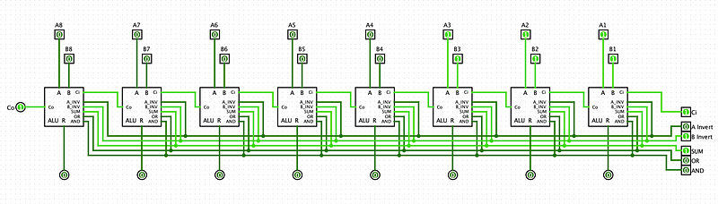
The result is 0000 0000 as expected. So we want to set our zero flag to 1 if and only if all of our result bits are 0. This means we need to build a circuit to check if all the bits are zero.
As you might recall an OR gate outputs 1 if at least 1 of its inputs are 1. This is exactly the opposite behaviour that we need, so we can use a NOR gate (an inverted OR gate).
You can also think about this in terms of formal logic. The value of the zero flag should be 1 (true), if and only if all output result bits are 0 (false). We can represent that like so:
Z = ¬R1 ∧ ¬R2 ∧ ¬R3 ∧ ¬R4 ∧ ¬R5 ∧ ¬R6 ∧ ¬R7 ∧ ¬R8
Using De Morgans Law, we get: Z = ¬(R1 ∨ R2 ∨ R3 ∨ R4 ∨ R5 ∨ R6 ∨ R7 ∨ R8)
So that confirms that we can use a NOR gate to check that all the result bits are 0.
In this gif, you can see that the NOR gate only outputs 1 if all the inputs are 0. Great, so all we need is an 8-bit NOR gate, and feed all the output bits from the adder circuit into the NOR gate.
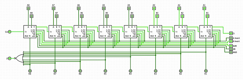
So now when we perform 7 − 7 on our ALU, the zero status flag quickly lets us know that the result is zero. This is useful because we don’t need to check that each result bit is zero.
Negative/Signed Flag (N)
The negative flag Set to 1 if the arithmetic result of an operation is negative. Naturally, this flag is only meaningful if we are dealing with signed operations. As you may recall, when we represent signed numbers in two’s complement form, the most significant bit acts as a sign bit. If the most significant bit is set to 1 then we know the number is negative.
For example, -5 in two’s complement is 1111 1011. The most significant bit (leftmost) is 1, which tells us that the number is negative.
We can use this fact to easily create a signed flag. All we need to do is look at the most significant bit and see if it is 1.
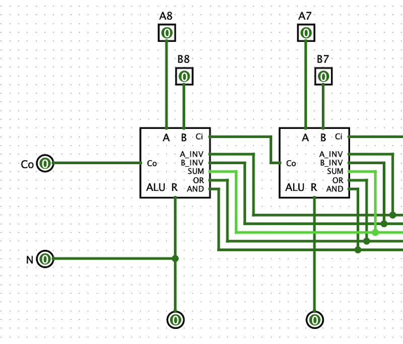
Now that we have a negative flag, we can easily check if the output is less than zero. This will come in very handy for comparison calculations.
Overflow/Underflow Flag (V)
The overflow/underflow flag is set to 1 if an overflow/underflow error occurs when we do a signed arithmetic operation. For example, when we are using two’s complement, the range of numbers we can represent with 8-bits is -128 (1000 0000) — 127 (0111 1111). So what happens when we try to do 127 + 1? We get an overflow error. If we actually try to do this operation on our ALU, the result would be 1000 0000, which is -128 in decimal. This is a result of us exceeding the maximum value we can store in 8 bits.
We can represent this visually like so
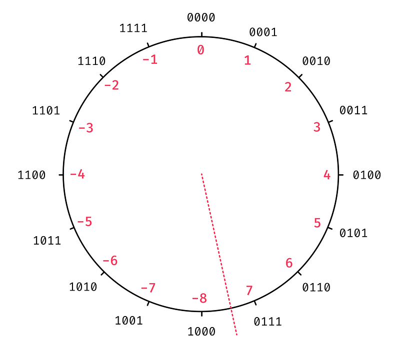
The red dotted line represents the boundary between positive and negative numbers. When we add a positive number (addition), we go clockwise around the circle, and when we add a negative number (subtraction), we go anti-clockwise around the circle.
So how can we check if we have an overflow error?
Comparing Inputs and Outputs
One way to calculate the overflow flag is to compare the input to the output of our addition operation. If both inputs are positive (e.g. 127 + 1) and the output is negative (-128), then we know an overflow occurred. Two positive numbers will never add together to produce a negative number. Similarly, if we have two negative inputs (e.g. -128 + -1) and the output is positive (127) then we know an underflow occurred. Two negative numbers never add up to a positive number.
Finally, in the case where we have one positive input and one negative input, we actually can never have an overflow occur. This is because when we add a positive number to a negative one, the output will never be greater than the positive number, and will never be less than the negative number. So this means we can never go out of bounds. For example 12 + (-4) = 8. As you can see, 8 is less than 12 and greater than -4.
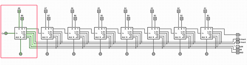
If we want to build a circuit that compares the input and output, the first thing we need to check is whether A and B have the same polarity. We can do this by comparing the sign bit of both numbers. So we take the most significant A bit and the most significant B bit and compare them. If they are the same then we know the numbers have the same polarity.
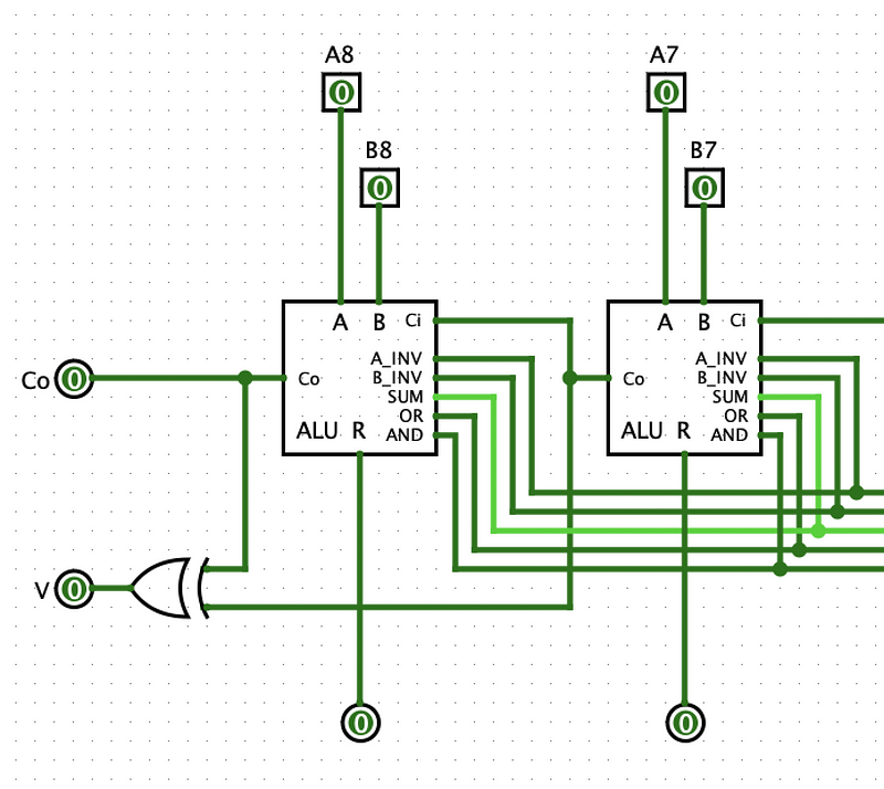
Conveniently the sign bits of the inputs and outputs are all the leftmost bits. This means we only need to concern ourselves with the leftmost 1-bit ALU block.
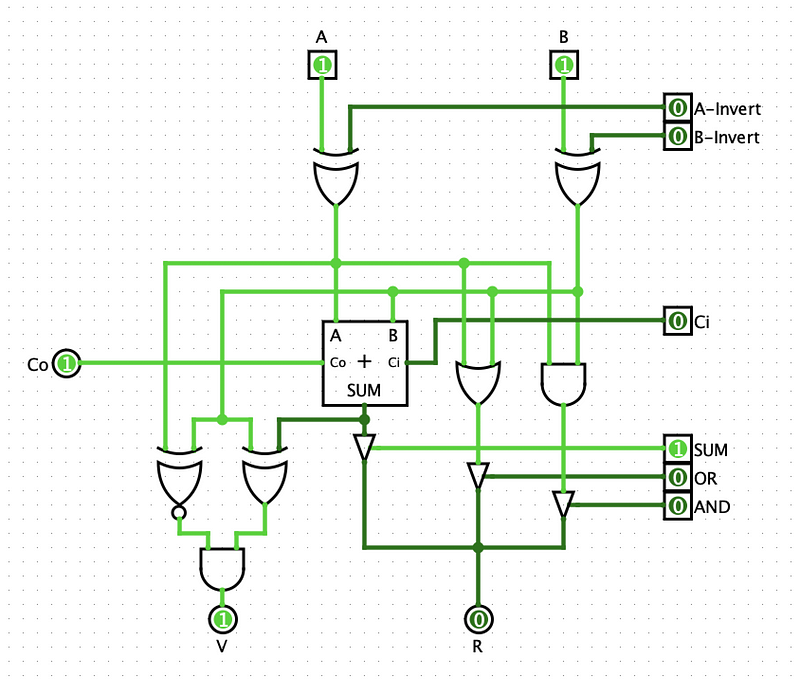
We will be looking at the internal circuits of this 1-bit ALU which we built in the previous part. First, we want to check that the sign bits (the A and B inputs) are both the same. If the sign bits are the same, we know that the two inputs have the same polarity. To check that two bits have the same value, we can use an XNOR gate. An XNOR gate outputs 0 if its inputs are different and outputs 1 if the inputs are the same.
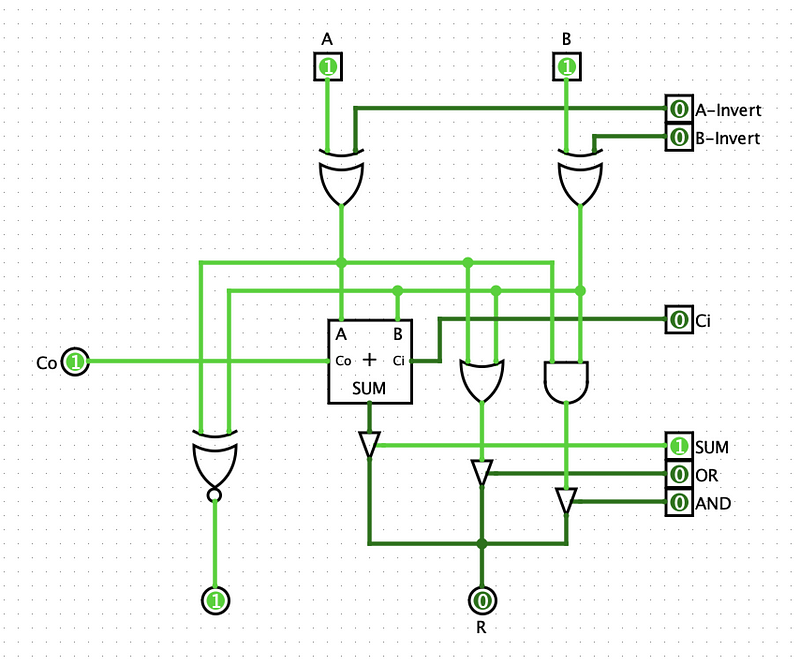
Now we also need to check if the input polarity is different from the output polarity. In this case, we want to check that two bits are different. So instead of an XNOR gate, we can use an XOR gate. We can take the value of the A input and the output of the adder and compare them. We could choose either A or B because we only care about the case where both A and B are the same.
So now we are checking if the two inputs have the same polarity (XNOR gate) and if the output has a different polarity (XOR gate). An overflow will occur if and only if both these gates output a 1. To check this, we can just use an AND gate to finish off the circuit like so:
This is pretty good, but there is a more efficient way to create the overflow flag circuit.
Comparing Carry Bits
Just like the previous method, we only care about the sign bits. Let’s have a look at a truth table for the full adder in the leftmost 1-bit ALU block.
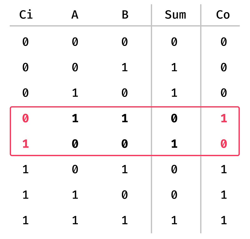
Here we have all of the possible values for the carry, A, and B inputs. I have highlighted the two results that cause an overflow/underflow. As you can see, in the first highlighted row, both A and B are 1, meaning both inputs are negative. But the sum output is 0, indicating that the output is positive. Similarly, the second row shows that A and B are 0 (positive), and the sum output is 1 (negative).
The other interesting thing is that if we take a look at the carry input and output for these rows, we can see that the input and output is not the same value. This property only happens when we have an overflow/underflow occur. So this means we can quickly check if we have an overflow by checking if the carry input is different from the carry output. We can use an XOR gate to do this.
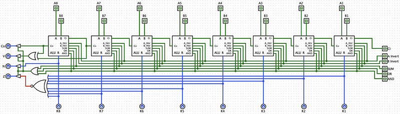
Putting It All Together
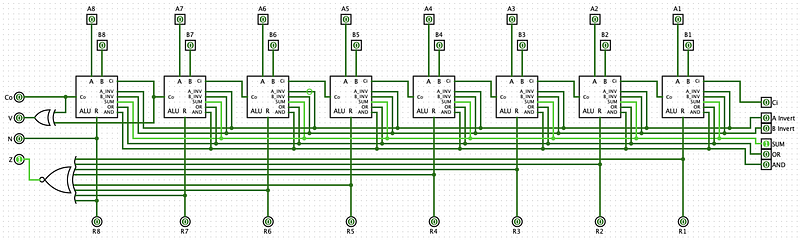
Now, whenever we do an operation on our ALU, we can quickly check some useful facts about the result by looking at the status flags.
The last thing that is left is only outputting a flag value if one of the operations is selected. If no operation is selected, we should just output nothing.
If we want to check that at least one operation is selected, we can use an OR gate. And we can use the output of that gate to turn on and off the outputs of the status flags. The circuit would look something like this. Each of the flag output has a controlled buffer that we can turn on and off using the output of the OR gate.
Awesome! Our basic ALU circuit is now fully equipt with status flags. In the upcoming sections, we will see how we can make comparisons with these flags, and also add our multiplication and division circuits.


