Building an 8-bit computer in Logisim (Part 2— Arithmetic)
In this part, we will be covering how to do all the standard arithmetic operations, addition, subtraction, multiplication, and division. We will also be covering other essential operations like bit shifting and circuits like multiplexers.
Addition
I know that we covered the adder circuit in the previous article, but I wanted to explore one more important topic, overflow error.
Overflow Error
What happens when we try and exceed the maximum value of an 8-bit number? Well, let’s have a look.

We start with the largest 8-bit number possible 11111111 = 255. Then we try and add 1 to it. As you can see for each column, we end up with 0 + 1 carry bit. This propagates all the way to the left-most column, and our final result is 100000000 = 256. However, we have a slight problem. We only have 8 bits to store a number, and 256 requires 9 bits. We have no space to store that last 1 in the 9th column. This means we end up rolling back over to 0. A real-world example of this is a tally counter that has reached 9999.

If we were to click the counter one more time, the display would reset back to 0000 because it can’t display 10000.
This is called an overflow error. It is quite an important concept because it is the source of a lot of mistakes, but it can also be very helpful as we will see in the next section.
Subtraction
So let’s tackle subtracting numbers in binary. As you probably know, subtraction can be represented as adding a positive number to a negative number. For example 10–6 = 10 + (-6). We already know how to do addition, so the real question is, how do we represent a negative number in binary? Let’s work through some possible solutions together. I feel this is more helpful than jumping to the answer so that you gain an intuition for how negative numbers in binary work.
Signed Bit
Let’s keep working with -6 for our examples. 6 represented as a 4-bit binary number is 0110. So our goal is to make a negative version of this number. What we can do is take the left-most bit and use that as a signed bit. 0 would represent positive, and 1 would represent negative.
For example if 6 = 0110 then -6 is 1110
Now it is important to note that with an unsigned 8-bit number we can generate numbers from 0–15 (2⁴ = 16 possible numbers). With a signed 4-bit number we can generate numbers from -7–7. This is still actually 16 possible numbers because we can represent 0 as positive and negative (+0 = 0000, -0 = 1000).
Yes, I know positive and negative 0 is a bit weird, but we now have a way of representing a negative number with a sign bit which lets us quickly check if a number is negative.
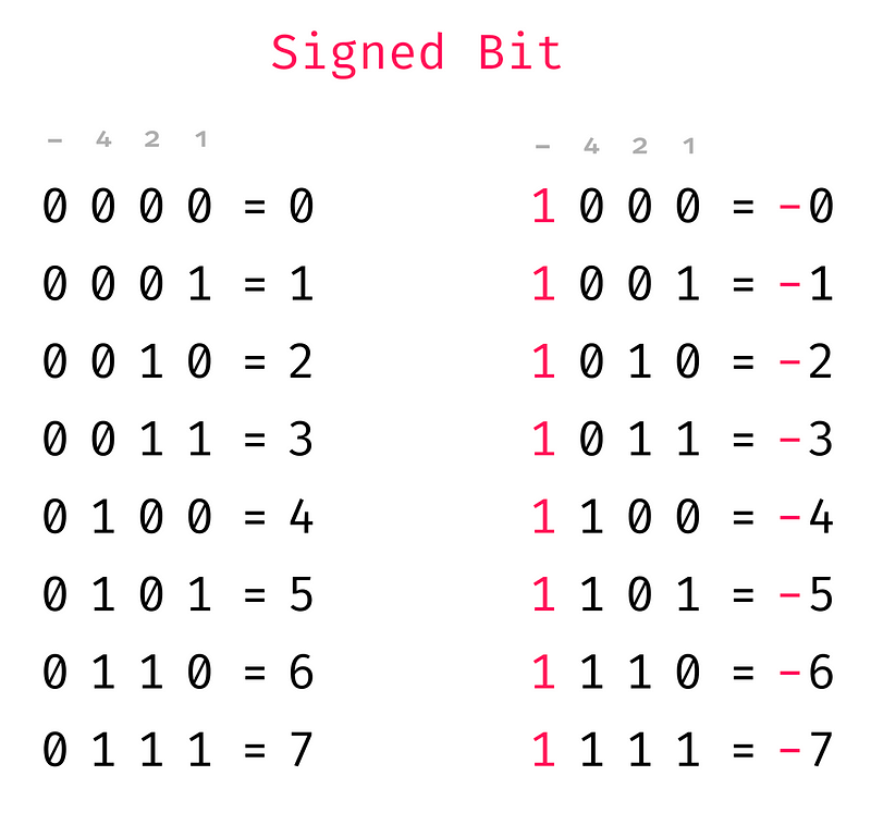
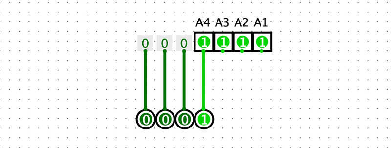
I have added at the top what each column represents. The first column to the right is the 1s place, and then the second is 2s, then comes the 4s and finally the signed bit. So take 1110, that is -(4×1 + 2×1 + 1×0) = -6.
One downside to this approach is a bit clunky when it comes to arithmetic. For example:

Here we are adding 3 and (-3) in our new signed number format, we know that 3+ (-3) should give 0, but instead, we get 1110 = -6
We could indeed build a complex circuit that did this calculation correctly, but it would be very messy. So let’s have a look at a better solution.
One’s Compliment
The sign bit was was pretty nice, but ideally, we want to be able to do arithmetic using our full adder circuit. One’s complement also uses a sign bit, but the method is a bit different. Instead of just inverting the sign bit (from 0 to 1) to represent a negative number, with one’s complement, we invert all the bits. That looks like this:

So now the left most bit still acts as a sign bit like in the previous method. With the ones complement the columns no longer match up to our -, 4s, 2s, 1s like it did with the sign bit. We have a nice property that addition works (sort of). Let’s look at some examples:
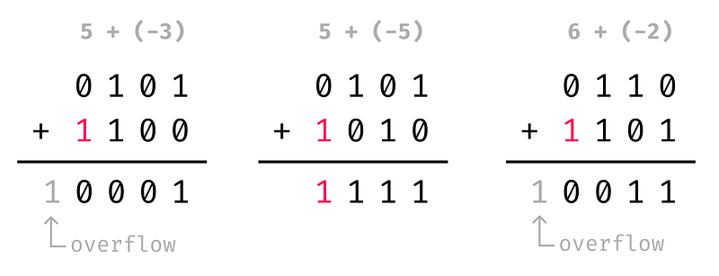
Note: keep in mind that the overflow bit can’t be stored in our 4 bits of space that we have, so it ends up disappearing.
So in the first example 5 + (-3) = 0001 = 1, then we have 5 + (-5) = 1111 = -0, and then 6 + (-2) = 0011 = 3. Now I know what you must be thinking, none of these additions give the correct value. Yes, but we are close. Each one of them is off by just 1. So if after the addition we just add 1 to each, we get the right value.
Two’s Compliment
If all of our additions are off by 1, what if we represent our negative numbers by taking the one’s complement and then adding 1.
For example 6 = 0110 so -6 = 1001 + 1 = 1010.
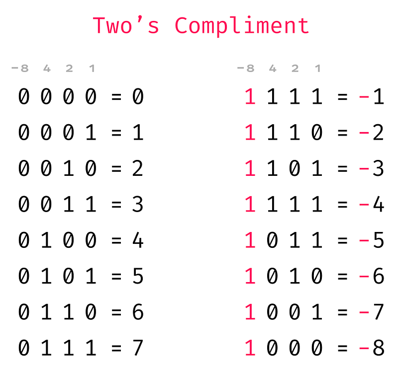
Two’s complement has several neat properties.
- The left-most column still acts as a sign bit, so we can quickly tell if a number is negative.
- All the columns line up to specific values, -8s, 4s, 2s, 1s. For example, take the number 1101. That is -8×1 + 4×1 + 2×0 + 1×1 = -8 + 4 + 1 = -3.
- There is no -0. This is because -0 = 1111 + 1 = 0000
- We have an extra number (1000 = -8)
- And most importantly, addition works perfectly with no weird side effects

Now 5 + (-3) = 0010 = 2, 5 + (-5) = 0000 = 0, and 6 + (-2) = 0100 = 4.
Awesome! So we now have a good way to represent negative numbers that works well for arithmetic also. The next step is to create a circuit that converts a number into its two’s complement form.
Building a subtraction circuit
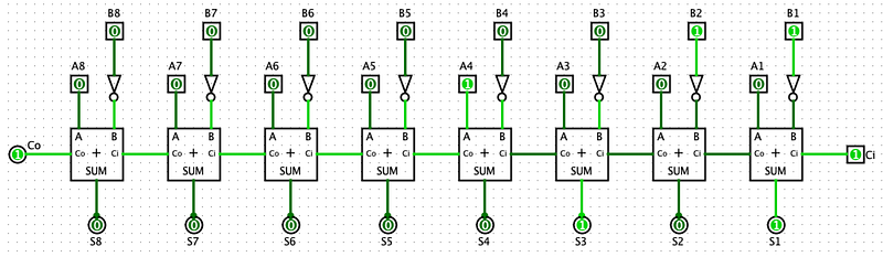
I am going to switch back to 8-bit numbers now. So to convert a number into two’s complement, we can use the 8-bit adder that we have previously built. If we invert all the inputs for number B, that does the first step (invert all bits). Then for the second step, we can pass 1 into the carry bit. This effectively adds 1 to the output.

And just like that, we convert 6 (00000110) into -6 (11111010)
We can do one step better, and use this circuit now to do subtraction as well.
If we just put in a number in the A inputs, then we end up subtracting B from A. Lets try that out with 6 – 6:

Just as we expect 6 – 6 returns 0. Let’s do one more example for good measure:
Here A is 8 (0001000), and B is 3 (00000011). And this correctly returns 5 (00000101).
Addition and Subtraction in The Same Circuit
As you might have noticed the addition and subtraction circuits are very similar. The only difference is that the subtraction circuit inverts the B inputs and sets the carry input to 1. Let’s build a circuit where we can toggle between addition and subtraction.
The first thing that we need to build is programmable NOT gate, something that can toggle inverting the input data. Thankfully there already exists a logic gate that does that exact thing. An XOR gate is 0 if both inputs are different, and 1 if both inputs are the same. Have a look at that in action:
So now we can use that to build an addition and subtraction circuit. Instead of inverting all the B inputs, we can just use an XOR gate to invert them conditionally. Lastly, we need to feed 1 into the carry input. We can simply do that by feeding the XOR toggle into the carry input as well like so:
When we set the ADD/SUB to 1, all the B inputs get inverted, and 1 is fed into the carry input. This circuit will, therefore, perform a subtraction (A — B). When ADD/SUB is set to 0, the B inputs don’t get inverted and so this will perform an addition (A + B).
Cool! That is addition and subtraction sorted! Let’s move onto multiplication and division.
Multiplication
A few quick notes about this section. Firstly, the 8-bit multiplication circuit takes up a lot of space, so I will be sticking to a 4-bit multiplication circuit. It will hopefully be clear how this can be easily extended. Secondly, because we will be dealing with individual bits of the two factors and the product, let’s label each bit like so:

Here A and B are the two factors, and P is the product.
Alright, buckle up because it’s going to get wild from here on. So, let’s think about how multiplication works. Say that we want to calculate 4×3. We can do that with a series of additions, 4 + 4 + 4 or 3 + 3 + 3 + 3. We already have a circuit that does addition, so we could do multiplication this way. Let’s have a look at multiplication in binary to see if we can get any more clues about how to create our circuit.

Binary multiplication is done exactly how you would do normal multiplication. First, we calculate all of the partial products. Note that in binary this is particularly easy because anything times 1 remains the same, and anything times 0 becomes 0. For example:
- 1110×1 = 1110
- 1110×0 = 0000
Easy right! Then after we calculate all the partial products, we shift each one over as shown in the gif above, and then sum them together.
So we need to find a method that lets us calculate the partial product.
We need some circuit such that B×1 = B and B×0 = 0. If you are familiar with your logic gates by this point, you might have recognized that we can use an AND gate for this.

As you can see, when B is 0 the output is 0. When B is 1 the output is whatever A is. Perfect!
So to calculate the first partial product (PP) of A×B, we take the first bit of A (A1) and then AND it with all the bits of B.
Let A= 0101 and B = 1110
PP1 = A1 AND B1 = 1 AND 0 = 0 PP2 = A1 AND B2 = 1 AND 1 = 1 PP3 = A1 AND B3 = 1 AND 1 = 1 PP4 = A1 AND B4 = 1 AND 1 = 1
So the 1st partial product is 1110.
Our circuit would look like something like this:

Notice that A1 is fed into each AND gate along with one bit of B. We can repeat this process for all the other partial products. That would look something like this:

Now that we have all of the partial products, we need to shift these partial products and sum them up. Let’s start with the 1st and 2nd partial products together. Let’s call the first partial product C (C4, C3, C2, C1), and the second we will call D (D4, D3, D2, D1).
So then if we look at the gif showing the multiplication process, we can see that we need to shift one of the products so that we end up adding C2 to D1, C3 to D2, C4 to D3, and D4 to 0. This operation is equivalent to shifting C by one bit to the right and adding it to D. We also save the first bit of the 1st partial product (C1) because this will become the 1st bit of our final product (P1). And we can see that D1 + C2 gives use the 2nd bit of our final product (P2).

To perform this bit shift and addition in a circuit, we can use the full adder that we have built in the previous article.

Notice how the 1st partial product is shifted to the right by 1 bit at the input of the full adder. And the first bit of the partial product and sum output have been labelled P1 and P2 respectively.
Now, all we need to do is take that output sum of this circuit shift it to the right, and add it to the 3rd partial product, and so forth. Let’s build a circuit that does this whole process.
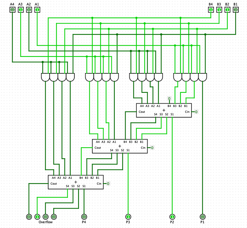
As you can see, the first bit of each of the sum outputs makes up part of the final product. After the final adder, we are left with 4 bits. These 4 bits are our overflow bits. The largest product that we can create with two 4-bit numbers is 1111×1111 = 11100001 (This is 15×15 = 225 in decimal). As you can see 11100001 requires eight bits to store, so we end up with four overflow bits (1110) and 4 product bits (0001)
And there you have it. A full 4-bit multiplier. It might look a bit intimidating, but hopefully, you can see the individual components that make this up and have a better understanding of what everything does. In summary, all that binary multiplication is a series of right binary shifts and additions.
I think it is kind of cool that if you compare this circuit to the original gif showing the multiplication process, you can sort of see the same structure.
OK cool! let’s move on to division
Division
Brace yourself because the division is the most complex of them all. But we will be building on concepts that we have learnt from the previous operations. We know that division is the opposite of multiplication. So if multiplication is just bit shifts to the right and addition, then division is just bit shifts to the left and subtraction.
But before we get to far ahead of our selves, let’s familiarize ourselves with some terminology and take a look at binary division in action.
Terminology

Divisor — The number that we divide by Dividend — The number that is being divided Quotient — The amount produced by the division of two numbers Remainder — The amount “leftover” after performing the division
Just like with the multiplication section, I will be referring to individual bits of the divisor, dividend, quotient and remainder. To make this easier I have labelled each bit like so:
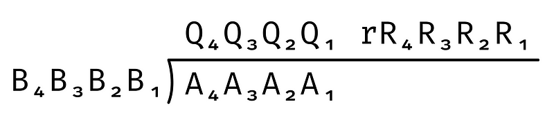
Process of binary division
The method of binary division is pretty much the same as long division. If you need a quick refresher here is a good tutorial. And here is a gif that shows the process of binary division.
In this example we want to divide 1111 by 0110.
Step 1. We take the left-most bit of the dividend (A4) which is 1 and see how many times the divisor (0110) goes into it. 0110 is much bigger than 1, so it doesn’t divide evenly, and so we get 0. This 0 will become the left most bit of our quotient (Q4).
Step 2. We multiply 0110 with Q4. If Q4 is 0, then anything times 0 is 0, if Q4 is 1, then anything times 1 is just itself. In this case, Q4 is 0, and so we get 0.
Step 3. We now subtract this 0 from A4 giving 1. This 1 makes up the first part of the interim dividend. The second part comes from adding A3 to the end of our interim dividend. This gives us an interim dividend of 11.
Step 4. Now we see how many times the divisor (0110) goes into our interim dividend (11). Again this is 0 times. This result makes up our second bit from the left of the quotient (Q3).
Step 5. Now we repeat this process until we have calculated all the bits of the quotient. So we subtract 0 from the interim dividend to and add A2 to the end to get the next interim dividend, and so forth.
Step 6. If we are left over with a number greater than 0 from our last division, then this becomes the remainder. From the gif above you see that we are leftover with 0011. This means 1111 / 0110 gives a remainder of 0011.
Creating a Circuit
So the first step of the process is getting the left-most bit of the dividend. In our example, we have been dealing with a 4 bit number. So taking the left-most bit (A4) is the same as the number 000A4.
We can do this by taking three 0s and adding A4 to the end. Yes, this might seem trivial, but it is an important first step.
Now we need to see if the divisor (A) divides B4. What we can do is check if A is less than B4. If this is the case, then A divides B4. One neat property of the subtraction circuit we built is that we can use it to see if one number is greater than the other.

As you can see when A is equal to or greater than B the output carry bit becomes 1. This makes sense because if we convert 0111 into one’s complement, then we get 1000. Then adding 1 to get twos compliment gives 1001. Now adding 1001 and 0111 together, we get an overflow error. That is what the output carry bit is representing. More generally, if B is equal to or greater than A, then we get an overflow error. This fact is handy as we can use it to see if B goes into A.
Alright, now back to our division. We can now check if B goes into A4 like so:

In this case, we can see that the output carry bit is 0. Which means that A4 is less than B, and therefore B does not go into A4.
Next, if B goes into A4 then we want to multiply by 1; otherwise, we multiply by 0. Then we subtract that product from A4. This is the same as saying if B goes into A4 subtract B from A4, otherwise don’t.
Looking at our current circuit we can see that we already perform A4 — B. So what we want is if the output carry bit is 1 use the difference calculated from the subtraction, otherwise, just use A4 again.
This is a common problem where we have two options that we need to choose from that depends on something being a 1 or a 0. Let’s build a circuit that lets us choose from two options. This kind of circuit is called a multiplexer.

When we toggle the switch, we are switching to output between A and B. We use this circuit to create a multiplexer for multi-bit inputs.

Here we simplify the 1-bit multiplexer into trapezoid symbol, but you can see how we can easily build a multiplexer for however many bits we need. So lets now use that in our division circuit.

So we are now using the output carry bit from the subtraction to select the output of the subtraction if the carry bit is 1 and A4 if the carry bit is 0. In this case, the carry bit is 0 and so the circuit selects A4. One other nice thing is that because the carry bit tells use if B goes into A4, it also gives us the left-most bit of the quotient (Q4).

So as you can see we have duplicated our subtraction and multiplexer circuits. There is something slightly tricky happening with the output of the first multiplexer. Let’s call this output M. You can see that M is being fed into the second subtraction circuit, but all the bits are shifted to the left by 1, and A3 is being fed in as the right-most bit. This is because M3, M2, M1, and A3 make up the interim dividend. You can see this if we look back at the division animation.

The red 1 is coming from A3. The black 1 on the same line comes from the output of the multiplexer.
Alright I know that’s a lot to digest, but if you have made it this far, the rest is quite a bit easier in comparison. Now we just need to keep repeating this circuit for all the other bits of A.

And there we have it. A full 4-bit division circuit. You will see that the output of the final multiplexer becomes the remainder of the division. In a future article, when we discuss the arithmetic logic unit (ALU) of the CPU, we will see how we can use the quotient and the remainder individually for integer division and modulo operations respectively.
We made it!
I know that was a lot to process, but hopefully, you’ve gained a bit more of an intuition about how computers perform the basic arithmetic functions. I hope you enjoyed this article, stay tuned for part 3, where we discuss how to build the computer’s Arithmetic Logic Unit.


