Building an 8-bit computer in Logisim (Part 3 — Basic ALU)
This is the third article in a series. If you haven’t read part 1 and 2, you can find them here:
In this part, we will be looking at how to build the Arithmetic Logic Unit (ALU).
What is an ALU?
The arithmetic logic unit is the part of the CPU that deals with doing arithmetic calculations. It is a combination of many arithmetic circuits that all work together to perform these calculations.
Typically, an ALU accepts two input numbers and lets you select the operation you want to perform. It then does the operation and outputs the result.
What should our ALU be Able to Do?
This sort of depends on the computer you want to build. Maybe you are making a basic computer, and all you need is addition and subtraction. Or perhaps you need something more elaborate that can handle a wide range of operations.
In this section, we will be making an ALU that can add, subtract, and make logical comparisons (AND, OR, NOT, etc.). In a future section, we will be extending our ALU to also include multiplication, division, comparisons and bit shifting.
Building a 1-Bit ALU
To keep things simple, let’s start with a 1-bit ALU. This ALU will take in two bits, (A and B) and perform some operation. Once we have built a circuit that can do all the operations on two input bits, we easily chain multiple 1-bit ALUs together to handle larger numbers.
AND and OR
The most straightforward part of our ALU is the AND and OR operations. To compute these, we can just use an AND gate and an OR gate. We then feed A and B into both their inputs like so:
NAND, NOR and NOT
It would be great if we can also calculate the inverted gates NAND and NOR as well as have the ability to invert either the A or B input. We could achieve this by adding four extra gates like so:
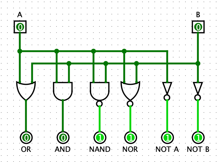
The problem with this approach is that we end up needing a lot more gates, and we also have gone from two individual outputs to six. So let’s look at a better way we structure our circuit.
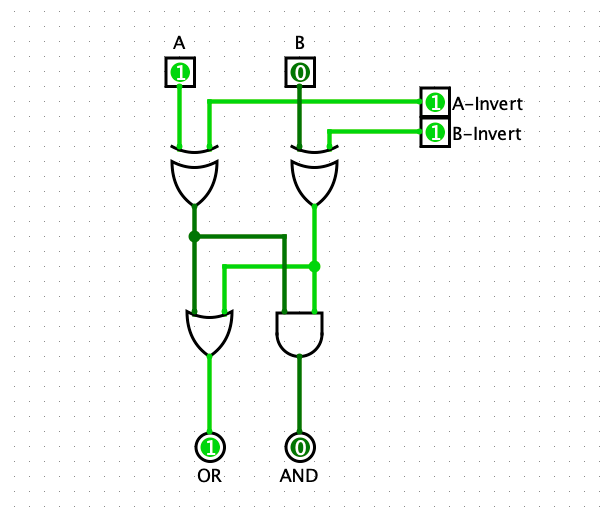
In part 2, we saw how we could use an XOR gate to invert an input programmatically. So using two XOR gates, we can add the ability to invert both A and B.

So if we want to invert B for example, we would set A to 0, and set the B-Invert to 1. Then The inverted value of B can be seen on the OR output.
So how does this help us get NAND and NOR? Well, our good friend De Morgan can help us out. If you haven’t heard about De Morgan’s Law, or need a quick refresher, here is a pretty good tutorial.
NAND in Formal Logic is ¬(A ∧ B). If we apply De Morgan’s Law, we get ¬A ∨ ¬B
So this means to calculate NAND we invert both A and B and look at the OR output.
In this image, if you look at the OR output, you can see that NAND, with inputs of 1 and 0, outputs 1. That makes sense because NAND outputs 1 as long as at least one of its inputs is 0. Great!
We can do the same thing for NOR.
NOR in Formal Logic is ¬(A ∨ B). If we apply De Morgan’s Law, we get ¬A ∧ ¬B
So just like NAND, to calculate NOR, we invert both A and B, but this time we look at the AND output.
Addition
To be able to do addition, we will use the full adder circuit we built in part 1.

Now we’re cooking! Adding the full adder means that we now have an input carry bit (Ci) and an output carry bit (Co). This will let us chain our 1-bit ALU together into an 8-bit ALU.
Subtraction
If you recall from part 2, we can perform subtraction using a full adder. To do this, we need to invert B and set the input carry bit to 1. This process inverts the sign of B using twos complement form. Because we can already invert our inputs, and we have control over the carry input, we get subtraction for free.
Selecting the Output
At the moment, our ALU has three individual outputs. Ideally, we want to be able to choose which output we want. So to do this, we will add a controlled buffer on each of the output wires. This acts as a switch, letting us turn on and off each output.
If no output is selected, then the ALU doesn’t output a result, but if we, for example, select SUM then the ALU will output the result from the full adder.
Awesome! Now we will package this circuit up and represent it like so from now on:
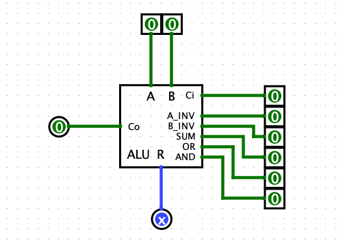
Building an 8-Bit ALU
Now that we have our 1-bit ALU, all that is left is chaining eight of them together.
We need to feed the output carry bit into the input carry bit of the next ALU block. And then we connect all the control inputs so that we can easily control the whole ALU.

And just like that, we have finished our basic ALU!
Next Steps
In the next parts of this series, we will be adding status flags, that quickly tell us useful information about our arithmetic operations, and we will be extending our ALU to also be able to handle comparisons, multiplication and division.


