Building an 8-bit computer in Logisim (Part 1 — Building Blocks)

Last semester I built a basic 8-bit computer in Logisim. This all started because of a course that I took last semester at uni called Introduction to Computer Systems. This class is used to be three separate classes which got melded together into one. It was a LOT of information to absorb, everything from Assembly to the OSI model to analogue and digital signal processing to logic gates.
Logic gates really interested me. I had seen them before but had not given them much thought or knew what they were. By this point in my degree, I was familiar with AND and OR in programming. But seeing logic represented in circuits was new and exciting.
My lecturer mentioned this program called Logisim which was like a playground for logic gates. So when I really should have been finishing my Programming Fundamentals assignment, I downloaded Logisim and had a play around. I remember thinking to myself, “I just want to make an 8-bit adder”. But let’s just say I got hooked and after a week of ignoring my other assignments, I had built a basic 8-bit computer in Logisim.
In this part of the series, I want to layout the primary building blocks that I used to create the computer, and hopefully, show you how cool logic gates are.
There are 4 main things that we need to build almost everything else:
- A way to do basic arithmetic (adding)
- A way to keep everything in sync (clock)
- A way to store data (memory)
- And a way to select from multiple options (binary decoding)
I am going to assume you have a basic understanding of logic gates and their symbols. If you haven’t seen them before here is an awesome introduction.
All right, let’s get started!
1. Basic Arithmetic (Adding)
As we will see later, all of our math operations can be done with addition. Addition is super powerful, and once we crack this, in later parts, we will tackle subtraction and multiplication.
Half Adder
So the first problem to tackle is how do you add two numbers together? Let’s start with a really simple task, 1 + 1. To do this, we can create a simple circuit called a half adder. It’s called a half adder because as we will see later, a full adder circuit uses two half adders. A half adder is missing some of the functionality of the full adder.
This circuit has two inputs, number A and number B, and it has two outputs, the sum and the carry. For example, if we add 1 and 1 together, then we get 10 in binary. The 0 would be the sum and 1 would be the carry. Now that we can add two 1-bit numbers together, let’s build a full adder so that we can do more complex addition.
Full adder Adder
The full adder extends on the half adder by adding a carry bit input. This means that later we can string these together and add multi-bit numbers together. As you can see the full adder is constructed from two half adders.

This circuit is a bit more complex, but basically what this circuit accomplishes is adding three 1-bit numbers together. For example 1 + 1 + 1 = 11 in binary.

Adding Bigger Numbers Together
Now that we have a full adder, we can move on to adding multi-bit numbers together. Let’s start with adding two 2-bit numbers together. To do this, we can string two full adders together like so:

To simplify the diagram, each square represents one full adder. The carry bit output of the adder on the right feeds into the carry bit input of the adder on the left.
So now we can repeat this process and string 8 full adders together.

With this setup, we can add two 8 bit numbers together. This gif shows adding 00101011 (number A) and 10001110 (number B) together. You can see when a carry bit is being passed from one full adder to the next when the horizontal line that connects the squares light up. As you can see from the output bits, the result is 10111001.
Great! This circuit is going to be VERY useful down the line.
2. Keeping everything in sync
So you might have heard of CPU clock speed. But what is that? All that a clock is is a mechanism that ticks at a specific interval, switching between high (1) and low (0). The CPU clock speed is simply how fast this mechanism ticks between 0 and 1. Modern CPUs have speeds of 4.5Ghz and up. This means that a modern CPU has a clock that ticks 4500000000 times a second. That is insanely fast.
This is how we represent a clock in Logisim:

I have attached an output bit to the clock to see how the value changes as the clock ticks, but we can connect this clock to any component we want.
The Clock’s Rising Edge
In our computer, we want to be able to use our clock to keep everything else in sync. One common way to do that is to use the rising edge of the clock as a trigger.

I have highlighted the rising edge of the clock in red. So the next challenge is to build a circuit that detects this rising edge. Ideally, we want to create a square wave that has a very short pulse each time that the clock goes from 0 to 1. That would look something like this.
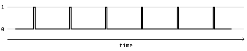
Rising Edge Detection
We can build a circuit that detects the rising edge of the clock quite simply. It looks like this.
I know it looks like this is not doing anything. But the three NOT gates have a VERY short delay before inverting the input. So for a couple of nanoseconds, both the inputs to the AND gate are 1. This creates a very short pulse on the output. We can use that pulse to trigger actions in our computer.
3. Storing Data (Memory)
Just like how we write things down as we are calculating a complicated math problem, our computer needs to be able to store numbers and instructions.
Latching Circuits
Our next goal is creating a circuit that “latches”. What I mean by this is a circuit that can save data. This will let us build memory for the computer.
Let’s have a look at a super simple example.
This circuit loops back on its self, and once we turn on the data input switch, you can see that the output will always be on. This on its own is not super useful, so we need a way to toggle the state of the output.
S-R Latch

This circuit is called an S-R Latch because you can set and reset it. Pressing the set button sets the output to 1 and pressing the reset button sets it back to 0.
This is great, but it would be nice to be able to save the state of an input value (either 0 or 1) to the output, rather than having to press a set or reset button. For this, we can use a D Latch.
D Latch
This circuit is called a D Latch because it latches the data input. Unlike the S-R latch, this circuit has an enable input. As long as the enable input is on, then the circuit will latch whatever the data input (D) is. If the enable is off, then toggling the data input does not affect the circuit.
The next thing to do is sync this up with the clock.
D Flip Flop
With the rising clock edge detector we made earlier, we can build a D flip flop. A D flip flop is almost exactly the same as the D Latch, but it has a few slight changes.

The main thing that has changed here is that we have added the clock. Now when the D flip flop is enabled, the data only gets saved when the clock changes from a 0 to a 1. This means saving our data is now kept in sync with the rising edge of our clock. Just like the D latch, we can still enable and disable our circuit. This lets us store data for multiple clock cycles.
8 Bit Register (Storing More Data)
Now that we can store one bit of data, let’s build an 8-bit register that can store eight bits of data. As you might have guessed all we need to do is string eight D flip flops together.

In this gif, we are setting the value 00110110 into the register. First, we set all the inputs to the correct values. Then we enable all of the D flip flops. And then on the rise of the clock, all these values get saved.
Pretty neat huh! In future parts, we will use this to build the registers and the RAM of our computer.
As you can see this method requires a lot of logic gates for just eight bits of data. Logic gates are made of transistors, and so this is quite expensive. Real RAM is built using a different method to keep the cost down. But that requires the use of capacitors, which we don’t have in Logisim, so this will have to do.
4. Selecting from multiple options (Binary Decoding)
Later, when we build our ram, we are going to need to be able to select a specific row and column of memory. To do this efficiently, we need a binary decoder. The basic idea is that we take a binary number and convert it to a specific output. For example, with 2-bits of data, we can select from 4 possible options.
- 00 = option 1
- 01 = option 2
- 10 = option 3
- 11 = option 4
The amount of options grows exponentially as we use more bits. In Logisim, I built a 4-bit binary decoder which has 16 possible options. The circuit looks like this:

This gif cycles through all the possible states of the binary decoder. I know it looks like a huge mess of wires, but this circuit will become super useful very soon!
That’s all the building blocks!
I hope you enjoyed part 1. Stay tuned for part 2 where we will be looking at how we can perform more complex calculations using our 8-bit adder we built.


