Math in Network Packets
CM.5 Bits, bytes, and packet headers — starting with the ethernet header
Part of a series on Cybersecurity Math. Also, Network Security.
Free Content on Jobs in Cybersecurity | Sign up for the Email List
In the last post I showed you how to convert hexadecimal to binary and decimal using a formula I found online years ago.
In this post, we’ll take a look at network packet headers, the length of the ethernet header, and how to figure out where the IP header starts in a network packet.
Often when people explain packet headers they explain each packet header independently, one at a time. That approach confused me initially and I misunderstand a few things as a result. Like I explained in other posts, I understand things better in context.
I’m going to explain it a bit differently. We’re going to explore the packet headers as a group and their purpose within a networking stack. Then we’ll start looking at the math we need to find the data related to each layer in a network packet.
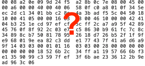
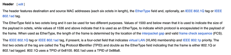
A network packet displayed in hexadecimal format
The packet below comes from a post I wrote about packet sniffing. This is a single packet displayed in hexadecimal (commonly called hex). How would you translate that back to something you can understand? Well, you will need to know something about how packets are structured when they are sent over the network and why.
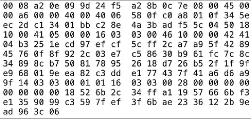
I remember the first time I saw network packets in this format. I attended a security presentation at Microsoft to hear a presentation about cybersecurity. An excellent presenter was explaining something I don’t quite remember — perhaps application attacks — and showing packets on the screen like this. I had no idea why he was showing us these packets and was somewhat in awe of his knowledge. Little did I know that one day I would be deciphering such things. You can too. :)
Network layers
The first thing you’ll need to know about packet headers is that they don’t only contain the data you are trying to send between systems. Network packets consist of layers of information.
Why? Because as the packet traverses the network, different types of network software and devices read the layers of data in the packet for which they are responsible. They will process the packet based on the information at that layer in the packet to get the packet to the correct destination — or reject or drop it if there’s something wrong with it.
For example, Routers act on the data at the Network Layer and the Data Link Layer. Network Firewalls often operate at the Network or Transport Layer. Application Firewalls usually operate on the data at the Application Layer after all the packets have been reassembled.
Many networking devices have combinations of functions and may operate across different layers in ways that don’t neatly map a device to a single layer. This always confused me at first because I wanted to neatly map each networking device to its own layer. It doesn’t really work like that. After writing this I read this tweet by Mick Douglas about how TLS doesn’t really map to a single layer either, which got me thinking, but we’re going to keep it simple for now so I can show you how the math works. The math will work with any variation of network protocol and standard.
The layers of data in a network packet are also beneficial because they increasingly validate the data in the packet. If something is wrong at one layer, the device processing the packet won’t proceed to the next layer. That’s why, though stateless firewalls that only look at IP addresses and can be easily bypassed by certain attacks, they can help you more efficiently block a DDOS attack. They don’t have to reassemble packets to block and IP address. Side note: It’s interesting that only AWS has a stateless VPC NACL. GCP and Azure only offer stateful options for blocking traffic.
A packet will have different information at the following layers (this is not a complete list of what you might see at each layer):
- Ethernet (Data Link Layer or Link Layer)
- IP (Network Layer or Internet Layer)
- TCP / UDP (Transport Layer)
- DNS / HTTP (Application Layer)
So for example, the layers in an HTTP packet might look like this:
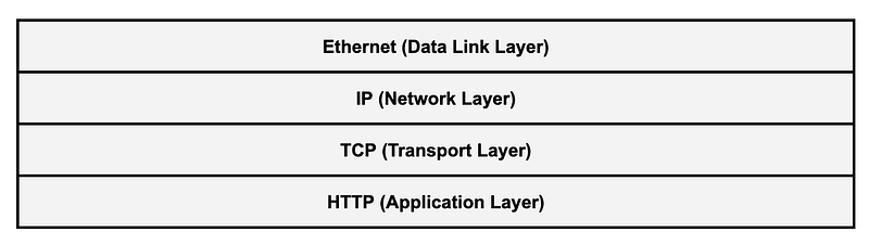
The layers (Data Link, Network, Transport, Application) are part of the seven layers of the OSI model which is often used to describe the different layers in a networking stack.
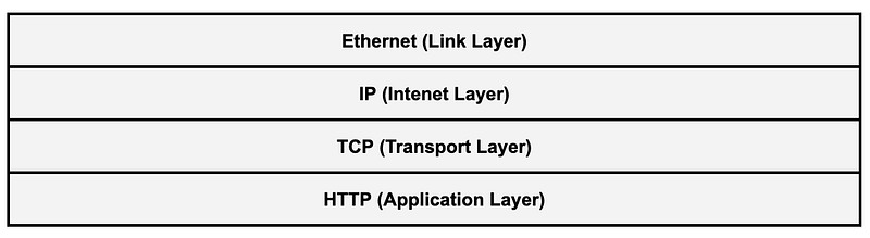
There’s another model with only four layers called the TCP/IP model. The concepts are the same but the names are of the layers are slightly different.
The rules systems follow to process at each layer is called a protocol. When systems create packets they are supposed to follow the protocols in use by the application and network devices involved in sending and receiving the packets and data. Protocols are defined in standards known as RFCs.
Packet headers
Each layer has protocols that define how a packet header should be constructed and added to the packet for that layer. The packet header contains data that tells networking software and devices how to process the packet and ultimately get it to the correct destination.
Some of the information contained in packet headers at different layers:
- The ethernet header contains the MAC addresses for the source and destination network cards.
- The IP header contains the source and destination IP addresses.
- If the network stream is sent using the TCP or UDP protocols those headers will contain the ports used to make the network connection.
- Finally, the application layer data may follow protocols that define how applications send requests and responses.
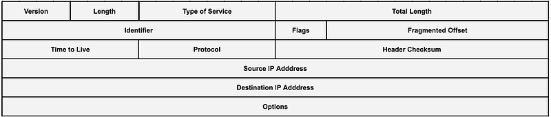
Here’s an example of all the data contained in the IP header:
Packet headers get added as the packet gets packaged and sent to the Internet. Different devices along the way will look at different parts of the packet header to deliver the packet to its destination. When the packet reaches the destination host the packet headers are removed and the application processes the reassembled data contained in the packets for a particular connection.
There are two different version so IP — IPv4 and IPv6. Depending on which IP protocol we’re looking at the packet headers may differ. The way IPv6 works, different packet headers can be inserted between others in ways that IPv4 doesn’t support. For this post we’re going to consider IPv4.
What’s the length of the ethernet header?
Let’s say we want to take a look at the IP header in this packet. We know that the IP header follows the Ethernet header. But where does the ethernet header end and the IP header begin?
Here’s where the math comes in. In order to get to the IP header, we need to understand the order of the layers in the packet, which I’ve shown above. The packet starts with the ethernet header, followed by the IP header, and then the transport layer header, and then the application layer protocol and data.
In order to understand where the IP header starts, we need to know the length of the ethernet header. That way we can calculate where the IP header starts in our hexadecimal packet data. Once we figure out where the IP header starts, we can start converting that hexadecimal data into something human readable.
An RFC is a technical specification that defines a standard. For example, RFCs exist for network protocols as mentioned above. Although other sources on the Internet point to RFC 894 for the length of the ethernet header, I don’t see it here.
But what RFC defines that size? After digging around a bit I found this definition in RFC 826 for Ethernet Address Resolution Protocol (ARP). ARP is a protocol that computers on IPv4 local networks use to find each other.
This is not super obvious but the transmission layer is defined here:
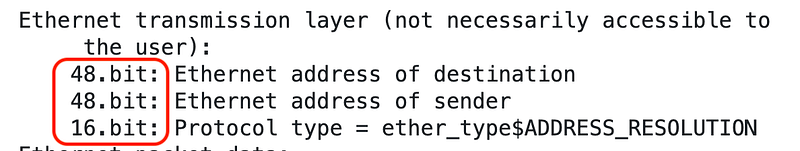
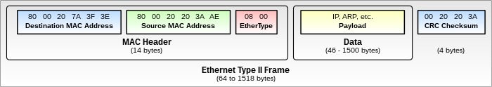
Essentially, the ethernet header contains:
- the MAC address of network interface card that is to receive the data.
- the MAC address of the network interface card that is sending the data.
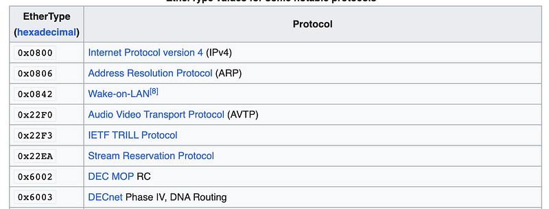
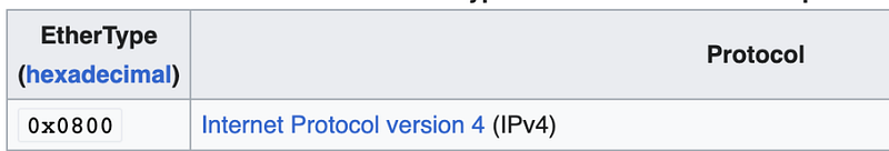
- Protocol type commonly referred to as EtherType.
There are different numbers or codes representing different protocol types in the next layer of the packet (the IP header). You can find a list of these codes on our friend, Wikipedia:
The point of all that was that by understanding the length of each piece of data in the ethernet header, we can come up with the total length of the ethernet header. (I’m skipping VLAN tagging for now.)
We can add the bits of the fields together: 48 + 48 + 16 = 112 bits
Now we know that the size of the ethernet header is 112 bits. But we’re looking at a packet represented in hexadecimal numbers. Also, that RFC was written in 1982. Most of the when people are discussing packet headers now they refer to packet header sizes in bytes.
Let’s consult the definition of the ethernet header on Wikipedia.
Huh? These descriptions do not need to be so complicated.
Scroll down on the Wikipedia page and we find the following picture which is a bit more helpful. The ethernet header (called MAC Header below) is 14 bytes long. The IP header follows.
Now we have a definition that says the length is 112 bits and one that says the length is 14 bytes.
What’s a byte?
This is going to be important to remember.
A byte is 8 bits.
In prior posts I explained that 1 binary digit is a size of 1 bit.
The following number is 8 bits, therefore it has a size of 1 byte.
1111 0000
There are 8 bits is a byte.
In a prior post I explained that one hexadecimal digit is 4 bits.
4 bits x 2 (hexadecimal digits) = 8 bits = 1 byte
There are two hexadecimal digits in one byte.
Using the information I already shared in prior posts, we can convert the binary number to a hexadecimal number.
0xF0
So F0 is two hexadecimal digits (F and 0) with a size of 8 bits or one byte.
In other words, F0 = 1111 0000 which has a size of 8 bits or one byte.
The size of two hexadecimal digits is one byte.
I am being intentionally repetitive to get that into your brain and mine.
That will be important to know as you are trying to decode network packets. If you remember that key point, your life will be easier when decoding network packets because often information is expressed in bytes but sometimes we need to convert the bytes back to bits for certain fields in a network packet.
What is the size of the ethernet header in bytes?
We know the ethernet header is 112 bits. How many bits are in a byte?
112 bits / 8 = 14 bytes
How may hexadecimal characters are in the ethernet header?
14 bytes x 2 hexadecimal characters per byte = 28 hexadecimal characters
Figuring out where the IP header starts
Now often you’ll hear people referring to the nth byte offset when talking about networking packets. Once again, this confuses my brain for some reason even though it’s not that hard if you think through it. The offset counting from zero where n is the last digit in the block of hexadecimal numbers or the first digit in the next block or…never mind. Here’s how I do it when I can, which I find easier.
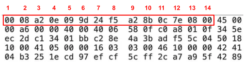
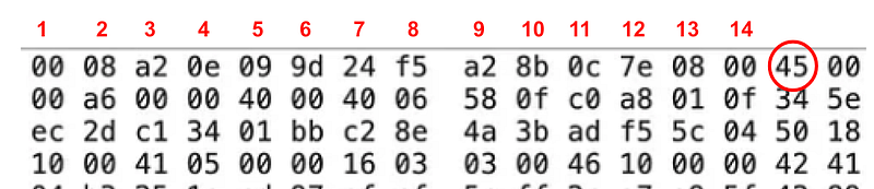
Now that we know that two hexadecimal characters equals one byte, we can easily count the first 14 byes of the packet. And those bytes represent the ethernet header. You could also count out 28 hexadecimal characters. But as you can see below Wireshark nicely splits up every 2 hexadecimal characters with a space, so it’s easy to count the bytes.
We can also determine which hexadecimal characters relate to each field in the ethernet header. From the RFC above we can get the length in bits and convert each length to bytes or the number of hexadecimal characters:
- Destination MAC: 48 bits / 8 = 6 bytes * 2 = 12 hexadecimal characters
- Sending MAC: 48 bits / 8 = 6 bytes * 2 = 12 hexadecimal characters
- EtherType: 16 bits / 8 = 2 bytes * 2 = 4 hexadecimal characters
Then we can use that information to determine which hexadecimal characters contain which values:
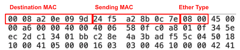
If you want to convert those hexadecimal characters to letters above you can figure out the MAC address in the packet. You can see that the Ether Type is 08 00 so that’s IPv4 in our list above.
Now we know that the IP header starts after the ethernet header so it starts with the characters 45 in the packet. But where does it end?
We’ll figure that out in the next post.
Follow for updates.
Follow for updates.
Teri Radichel | © 2nd Sight Lab 2023
The best way to support this blog is to sign up for the email list and clap for stories you like. That also helps me determine what stories people like and what to write about more often. Other ways to follow and support are listed below. Thank you!
About Teri Radichel:
~~~~~~~~~~~~~~~~~~~~
Author: Cybersecurity for Executives in the Age of Cloud
Presentations: Presentations by Teri Radichel
Recognition: SANS Difference Makers Award, AWS Security Hero, IANS Faculty
Certifications: SANS
Education: BA Business, Master of Software Engineering, Master of Infosec
Company: Cloud Penetration Tests, Assessments, Training ~ 2nd Sight Lab
Like this story? Use the options below to help me write more!
~~~~~~~~~~~~~~~~~~~~~~~~~~~~~~~~~~~~~~~~~~~~~~~~~~~~~~~~~~~~~
❤️ Clap
❤️ Referrals
❤️ Medium: Teri Radichel
❤️ Email List: Teri Radichel
❤️ Twitter: @teriradichel
❤️ Mastodon: @[email protected]
❤️ Facebook: 2nd Sight Lab
❤️ YouTube: @2ndsightlab
❤️ Buy a Book: Teri Radichel on Amazon
❤️ Request a penetration test, assessment, or training
via LinkedIn: Teri Radichel
❤️ Schedule a consulting call with me through IANS ResearchMy Cybersecurity Book: Cybersecurity for Executives in the Age of Cloud