Data Communication Made Easy
Important Science and Engineering subject that comprises analog and digital communication techniques for efficient networking
#SimplifyTheTech
How we live today has been transformed by data communication. What we couldn't do for centuries, we can do more effectively and fast in seconds and minutes today, all because of communication technology. Without this, you wouldn’t be able to watch your favourite TV show, listen to the radio, access the internet or even read this article explaining data communication.
Data communication is a very important topic for Science in Semiconductor Electronics. For engineering students, communication is a compulsory subject for all circuit-based branches like Electronics, Electrical, Computer Science, IT, etc. For others, this topic is something that we experience in our day-to-day lives, and a good understanding of it improves the way we use this technology.
This article, despite its complexity, has been decomposed for understanding by anyone without losing its essence and missing anything important.
Relevance of the subject
Data Communication is important if your aim is to work in networking, communication hardware and software, the telecommunication sector etc. Internet is an ever-growing field of inside data communication. Having a fast, reliable and robust communication system is more important than ever.
Updating technology is the biggest challenge in any field of engineering. Hence data communication helps you build a strong foundation in networking, digital technology, communication methods, etc. This will also help you choose your field of study in case of specialisation.
Prerequisites
This subject is quite beginner-friendly compared to a lot of other subjects. A mere understanding of computers and basic knowledge of physics and maths will be helpful in learning the subject.
What do you mean by communication?
Sending and receiving useful information is known today as communication. Popular forms of communication include oral, written, visual and a combination of all these. Today, as we speak of communication, the most important form of communication is considered to be data communication.
Data Communication
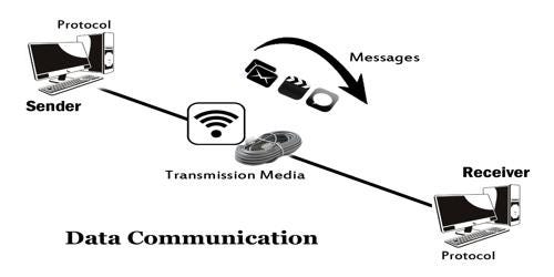
When communication happens with the help of an Electromagnetic Signal is known as data communication. There are two types of data communication- Analog communication and Digital communication. Data refers to units of communication in computers which are raw information. Signal refers to the method of transmitting data which is a form of energy.
Data can be in various formats- text, numericals, image, audio, and video. The flow of data can be in one direction, bidirectional with one side at a time and bidirectional. These are called simplex, half-duplex and full-duplex respectively.
A signal can be of two types: analog and digital. Analog signals are continuous waves, while digital signals are discrete waves. A signal has three properties- amplitude, frequency and wavelength. At a time, a signal can be represented either in Time or in the Frequency domain. Any signal whose values repeat in fixed intervals is known as a periodic signal. Well-known periodic signals are sine waves, square waves etc.
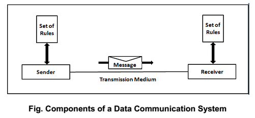
Communication System
Any system that is capable of sending and receiving data is called a Communication system.
Components of a Communication System
- Source
- Sender
- Receiver
- Destination
- Channel
- Network
- Transducers
- Signal
Characteristics of Data Communication
- Delivery- Understanding the route of the destination and ensuring that message is reached in the right place.
- Accuracy- Data transmission shouldn’t lose or alter any information.
- Timeliness- Timebound delivery of data not to lose its relevance.
- Jitter- Refers to variation in arrival of data.
Impairments in Data Transmission
- Attenuation (Loss of signal strength)
- Delay Distortion
- Noise
- Interference
Channel Capacity
Refers to the upper bound on the rate of information that can be reliably transmitted over a communications channel. Capacity is calculated using the Shanon Capacity formula: Capacity=Bit Rate x log2(1+ SNR).
Bandwidth
A measure of performance in a network. It is the frequency of the signal that can pass through a channel. Bandwidth is the difference of uppermost and lowermost frequency.
Throughput
The throughput is a measure of how fast we can actually send data through a network.
Transmission Media
It is the physical path through which data is transmitted. Just like electricity needs a conductor to travel, data is transmitted through medium or media. There are two types of transmission media- Guided and Unguided media.
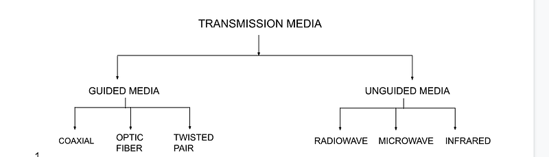
Guided Media
Utilises a specific physical path to transmit signals. Signals are bound by cables which guide the data flow. Guided Media is preferred for point-to-point communication. Different types of guided media include Twisted Pair, Coaxial cables and Optical Fiber Cables. This is quite cheap and easier to manage. Optical Fiber Cables are the best form of Guided media.
Unguided Media
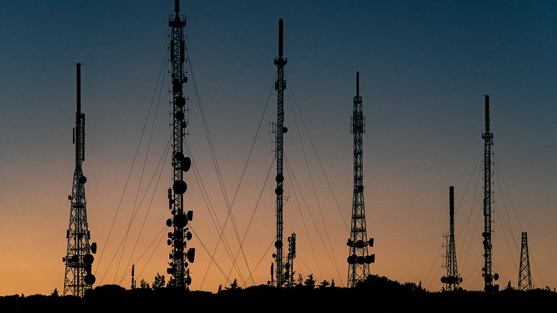
There is no solid medium or path for the signal to move. Air is the default medium for signal. Unguided media is preferred for broadcast communication. This is also known as wireless communication. Types of the same include Radio Waves, Microwaves- terrestrial and satellite, IR, Light and LASER transmissions. Unguided media is quite expensive.
Wireless propagation methods
Electromagnetic waves are highly energetic and invisible waves (except for visible light) which require a different type of propagation.
- Ground Wave propagation- Where the antennas are kept on earth vertically parallel to the surface.
- Line of Sight propagation- The antennas are kept directly at the line of sight to each other.
- Skywave propagation- The waves sent from the earth reflect back from the ionosphere part of the atmosphere and reach back to the earth.
- Space propagation- The waves sent from the earth enter space, reflect back with the help of satellites and reach the destination.
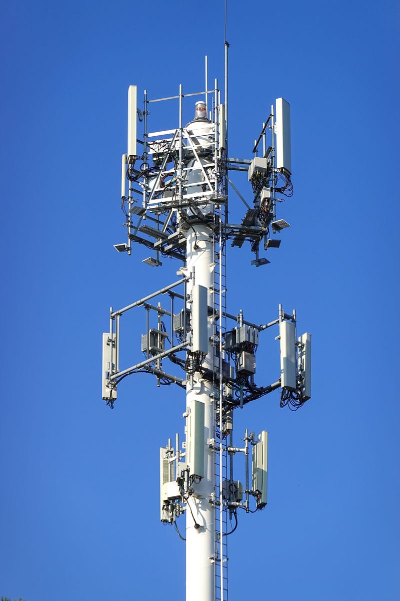
Satellites
It is a physical object that revolves around the earth. Artificial satellites have become more common, reliable and affordable today and are widely used for transmission. Three categories of satellites based on the altitude of their orbits are Lower Earth Orbit, Medium Earth Orbit and Geostationary Earth Orbit.
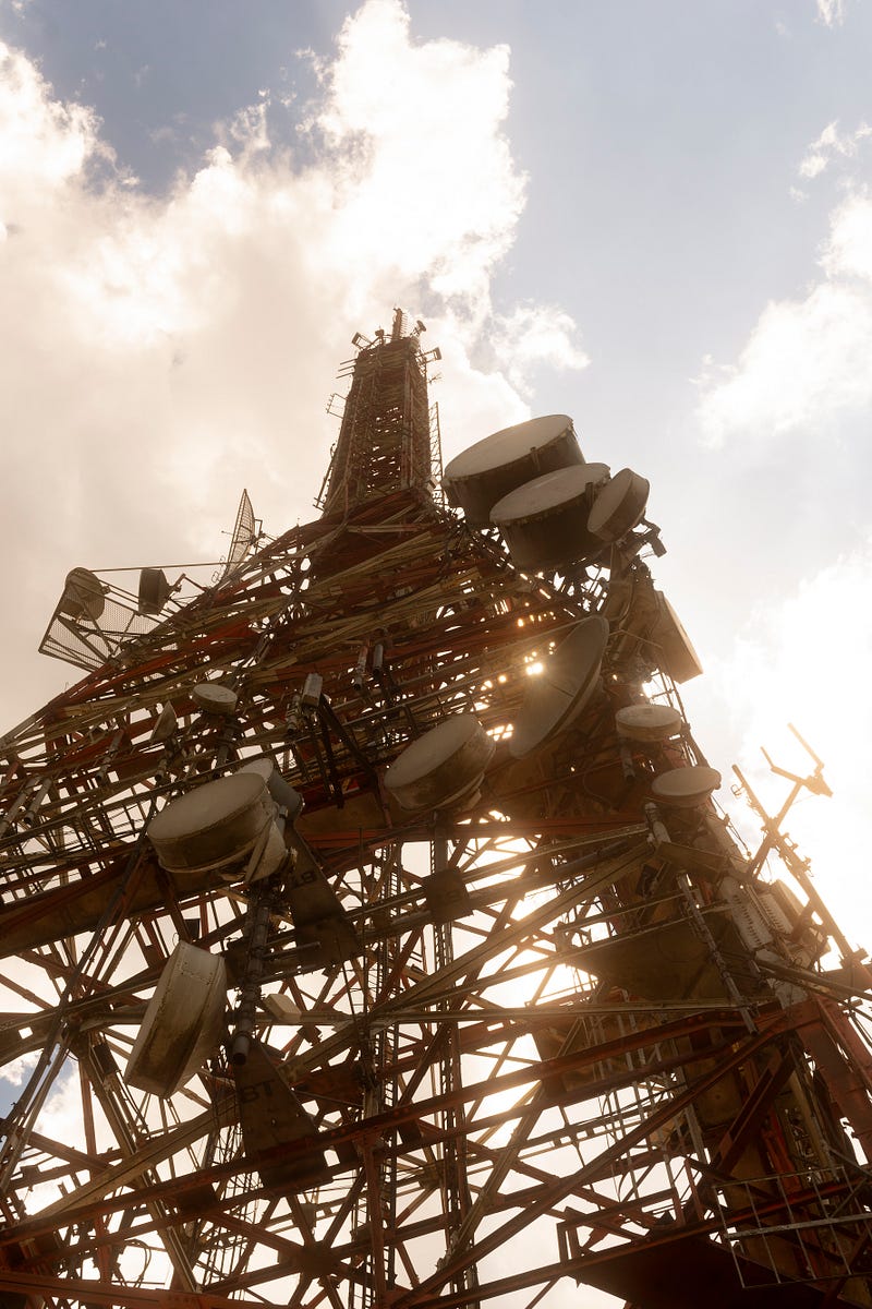
Antennas are the devices used for sending and receiving signals from satellites. Antennas are electric conductors that can radiate or collect electromagnetic energy. There are two types of antennas- parabolic dish antenna and horn antenna.
Encoding Techniques
Encoding is the process of using patterns of voltage and current levels to represent electronic information. Signal encoding is the technique used to convert data to signals.
Analog Data to Analog Signal Encoding
Modulation is a popular technique used to superimpose carrier and message signals. Modulation is done to ensure that signal travels with the same energy without losing its strength and also enables long-distance communication.
Analog encoding uses various modulation techniques to encode data. There are three main types.
Amplitude Modulation
Frequency is kept constant, and Amplitude is varied. Used for short-distance communication like a walkie-talkie, WiFi, WiMax, etc.
Frequency Modulation
Amplitude is kept constant, and Frequency is varied. Used for communication in general for big city and metropolitan area. We are familiar with FM radios.
Phase Modulation
Both Amplitude and Frequency are kept constant. Only phase is varied. Used for applications like Wi-Fi, GSM and satellite television.
Need for Modulation
This is a very important question for understanding the existence of the technique of modulation. There are three main reasons sighted for the need for modulation-
- Height of the antenna- should be kept minimal for sending the signals. If there were no modulation, antennas would have been kilometres long.
- Power dissipation of antenna- the more the length of the antenna and the lower the wavelength, the higher will be the power dissipation.
- Avoid interference from other signals- In an area, there will be tons of signals, noise and a lot more. So the signal needs to be powered to give strength to travel long distances.
Note- Modulation index (ratio of carrier and message frequency) is kept below 1 to avoid distortion.
Learn the history of Radio
Analog Data to Digital Signal Encoding
Varying voltage data is converted to a digital voltage signal. There are two main types of Analog to Digital Encoding.
Pulse Code Modulation
Analog data is converted to a digital code which is of the form 0s and 1s.
Delta Modulation
Analog data is converted to a digital code by using the staircase function.
Digital Data to Analog Signal Encoding
Digital data is encoded as Analog signals before transmission. Main Types-
- Amplitude Shift Keying
- Frequency Shift Keying
- Phase Shift Keying
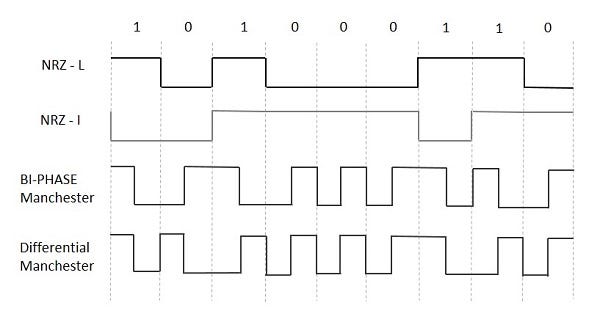
Digital Data to Digital Signal Encoding
Digital signals need specialised encoding in order to transmit long distances. Thus multiple techniques are used. There are three broad categories of the same- Multilevel Binary, Return to Zero and Non-Return to Zero.
These are all binary codes used in encoding, and there are various rules for the same, which are enlisted as given below.
Multilevel Binary
Uses Alternate Mark Inversion (AMI) and has three levels of encodings.
Non-Return to Zero
The code will not change if the bit is zero but will change only if there is a transition. Has two types- NRZ-L and NRZ-I.
Return to Zero
The code will not change if the bit is zero but will change only if there is a transition.
Biphase Manchester
Has a lot of types- Manchester and Differential Manchester Encoding. Combines multiple techniques.
Scrambling
It is a commonly used encoding technique which makes data retrieval very easy and provides synchronisation. There are two types of scrambling- Bipolar with8-Zero Substitution (B8ZS) and High-Density Bipolar 3-Zero (HDB3).
Multiplexing and Demultiplexing
Multiplexing is a process where multiple analog message signals or digital data streams are combined and sent as one signal over a shared medium. Multiplexing increases the efficiency of channel utilisation and also reduces the cost of hardware. Similarly, Demultiplexing is a process where a single signal is split into multiple lines in a medium. In short, Multiplexing is many to one, and Demultiplexing is one to many.
Frequency Division Multiplexing
It is a multiplexing technique that combines signals of multiple frequencies, adds them and sends them across the channels to the receiver. The channels are separated using guard bans to stop interference. At the receiver end, demultiplexing is done to retrieve back the carrier frequencies. FDM is an analog multiplexing technique.
Wave Division Multiplexing
Wave multiplexing allows multiple waves of different wavelengths to be combined into one and transmitted across the channel. Demux then converts the waves back into different wavelengths at first. This application is mainly used in optical fibre cables to provide high-speed internet.
Time Division Multiplexing
Just like in FDM, the channel will be divided into smaller channels for time, but the only difference is time is being divided here, and frequency remains the same. TDM is a digital multiplexing technique.
TDM is divided into two different schemes: synchronous and statistical.
Synchronous Time Division Multiplexing
Irrespective of the input, frames are allocated the same time slot. The number of slots will always be equal to the number of input lines. Synchronisation bits are there in each frame.
Statistical Time Division Multiplexing
Here time slots are allocated dynamically. The number of slots will always be less than the number of input lines. There are no synchronisation bits used here.
Code Division Multiplexing
Combines both FDM and TDM and utilises the channels, using specific codes for multiplexing of the channels. More features are incorporated here and used for CDMA.
Digital Carrier System
A carrier system is a telecommunications system that transmits information, such as the voice signals of a telephone call and the video signals of television, by modulation of one or multiple carrier signals above the principal voice frequency or data rate.
Spread Spectrum Technologies have become more common and relevant. The channel will be divided into multiple segments for different users. The following examples illustrate various types of Spread Spectrum based Multiple Access.
TDMA
Time Division Multiple Access divides time equally among different users, given that frequency is kept constant. This will allow multiple users to share a channel with the same frequency.
FDMA
Frequency Division Multiple Access divides frequency equally among different channels, given that time is kept constant. These are subscription-based services to users.
CDMA
Code Division Multiple Access divides the spectrum code among the different channels, given that other parameters are constant. This will allow messages to be broadcasted across the spectrum.
Modem
Cable TV is a commonly used broadcast medium in the world. Technology is so advanced that the same cable can carry the channels you watch on TV as well as for providing broadband internet. There are two types of data flow- Upstream and Downstream.
A modem refers to a device that can modulate and demodulate signals. Cable Modem can provide an internet connection to a massive number of people. The speed provided varies around 1.5 Mbps, but modern technology enables higher speed and also WiFi-capable modems.
Digital Communication
Till now, we talked about analog communication where signals have continuous values. Now, we talk about digital communication where data has discrete values. Thus, the mechanism for data transmission is also is distinct and unique. Unlike cables, the main hardware used for digital communication is a Bus.
Types of Digital Communication
There are two broad types of Digital Communication- Serial and Parallel Communication. In Serial Communication, bits are sent from sender to receiver serially, while in Parallel Communication, bits are sent from sender to receiver parallelly, i.e. multiple bits at the same time. One cycle means one clock pulse.
Due to more number of channels, Parallel Communication is faster than Serial Communication. But, since Parallel Communication has more hardware, it is more expensive.
There are two types of Digital Transmission. One which has Start and Stop bit for each byte is Asynchronous Transmission, and one which has a clock-based transmission is Synchronous Transmission. Synchronous Transmission is far superior to Asynchronous Transmission in speed, efficiency and accuracy.
Error Controls
A common issue associated with communication is a delay, loss of information and change in information. Error in Data Communication is referred to as any change in the data transmission from where it is sent and received. Two types of errors are Single-bit and Multiple bit errors.
Error Control means error detection and rectification. The best method used for error detection is the Parity Check, also known as Vertical Redundancy Check (VRC). Here for each byte (8 bits), one bit is used as the parity bit. For even numbers, the parity bit is 1, and for odd numbers, the parity bit is 0. In Longitudinal Redundancy Check (LRC), the parity bit is added at the end.
VRC does 50% of the error detection while LRC does the rest of the job. Cyclic Redundancy Check (CRC) uses a complex calculation to generate a 4-digit checksum which is added at the end of the message stream. The message stream added with CRC is known as Block Check Character (BCC).
Error Correction Methods
Once an error is detected, it has to be corrected and there are multiple methods for that. The first method is the Hamming Code and Hamming Distance method. The minimum Hamming distance is calculated through the XOR operation between the messages. No of the bits with error is calculated as n=(d-1)/2
Spread Spectrum
This method allows for the improvement of bandwidth efficiency by using special Spectrum Codes using a Spectrum Process. It provides security and accuracy to data transmitted.

Frequency Hopping Spread Spectrum (FHSS)
The system uses different carrier frequencies to communicate. Multiple frequencies are added to a Frequency table, and then a Hopping sequence is created with binary code using a pseudorandom generator. This output is fed to the modulator. The output obtained is a Spread Signal. Bandwidth can be shared.
Time Hopping Spread Spectrum (FHSS)
The signal is divided into different time slots, which are created using a pseudorandom generator. This output is fed to the modulator. The output obtained is a Spread Signal. THSS improves bandwidth efficiency.
Direct Sequence Spread Spectrum (DSSS)
The system uses special code to communicate. The system uses special codes, also known as Chip codes, to generate Spread Signal. Chip generator uses NRZ technique to encode bits. This output is fed to the modulator. The output obtained is a Spread Signal. Unlike FHSS, there is no bandwidth sharing.
Hybrid Spread Spectrum
A Spread Spectrum Technique combines DSSS and FHSS techniques to generate a Spread Signal. Thus, the technique uses a Hoping Sequence and a Pseudorandom number code generator.
Switching
A network is a web of interconnected devices. Even though we use the term connected, not all devices are connected to each and every device. Instead, connections are made possible using Switching. It makes it possible for a single device to establish a connection to all the devices without actually having a direct physical connection.
Benefits of Switching
It reduces the amount of hardware used, the cost of communication, efficiency and redundancy. Switches have the ability to establish temporary connections and enable the transfer of information.
There are three types of Switching-
- Circuit Switching
- Message Switching
- Packet Switching
Circuit Switching
It is a commonly used switching technique predominantly used in telephonic networks. This uses equipment and circuits to form a network. When communication happens, a physical connection is established between the sender and the receiver. Thus this method is purely a hardware-based connection. This method is used in the physical layer.
Only two users can communicate at a time, and if more users try to access, the connection will fail. Subscribers will have to pay for the service at all times, even if the connection is idle. Only a single protocol is used here. Coming to advantages, the capacity is fixed and features a strong connection once established.
The disadvantage of the same is the increased number of hardware, the damages caused, and wear and tear that can possibly occur. Establishing a connection can be time-consuming. Crossbar switches are the most used type of switches in the systems. Then there are multistage switches, time division switches, banyan switches and batcher banyan switches.
Message Switching
In message switching, each message is given independent status. Each switch has a storage space to store it before it is forwarded. Each message has the address of the destination, thus with the help of that, the message is forwarded to the next switch.
Message switching is quite complex and requires a lot of hardware storage space. It is not widely used as it is slow and cannot be used for real-time communication. It is used in Emails, which doesn’t need a real-time feature and a slight delay always occurs with the same.
Packet Switching
This is the most commonly used method of switching. Here, the messages are broken down into packets. Packets will have the address of both source and the destination. Packets independently take the path across the network to arrive at the destination. Each packet will also have numbering to ensure that packets are put back to order at the destination.
Unlike circuit switching, the protocols are complicated. Hence high powered processors are needed here. It is very hard for operators to charge the customers for the service they use. A significant advantage is improved bandwidth, and more users can use it at the same time.
Two approaches for Packet Switching
- Datagram Approach Here routers are in charge of switching, and packets are the carriers. Routers won’t store any information about the packets, and they can independently move and take any path to reach the destination. The movement of the packets is controlled by specific protocols. In this method, packets are referred to as datagrams. This approach is used in the network layer.
- Virtual Circuit Approach Just like Circuit switching, there will be a specific path for the movement of packets, followed by a fixed order. A single route is chosen, and all packets take the same one. During communication, a virtual circuit is established. This approach is used in the data link layer.
Data Communication from Exam point of view
This is an important subject if you are giving exams. This subject is the foundation for more in-depth topics like Computer Networks, OSI model, Network programming etc. You only need basic physics and mathematics to understand this subject.
Overall this is a theoretical subject; the scope for numerical is there for sure. Questions will be explanatory and essay-type. Practical problems can be asked from encoding, error check and correction, calculating frequency, bandwidth, channel capacity etc. This is indeed a scoring subject.
References
Forouzan, B. A. (2012). Data Communications and Networking (5th ed.). McGraw Hill.
Extra reading and references
Byjus, Geeks for Geeks, Tutorials Point, Electronics Notes
Also check out
Our entire KTU Academic Series
If you enjoy my content and find it informative, do support me at Buy Me a Coffee. My membership is only $1 per month, which means a lot to me and helps me present the best of the article. If you’re financially capable and willing to support me, please consider taking my membership, means a lot.
I have started a Telegram Channel which will contain the record of all my articles. Follow my blog for behind-the-scenes and informative content. Do join my medium mailing list.