
OLED Displays are SLOW!
We have been prototyping an Arduino based Electronic Speed Controller and planned to include a 0.96" OLED display. Tests on an Arduino UNO, clocked at 16 MHz, have shown that this display could best be described as sluggish! Even using SPI, printing out 3 lines of text results in a loop cycle time of 15 Hz. Quelle horreur! This prompted us to investigate further to understand the bottlenecks, SPI vs I2C speed, and whether there were any work arounds.
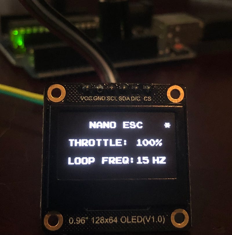
1.0 0.96" 128 x 64 Pixel OLED Display
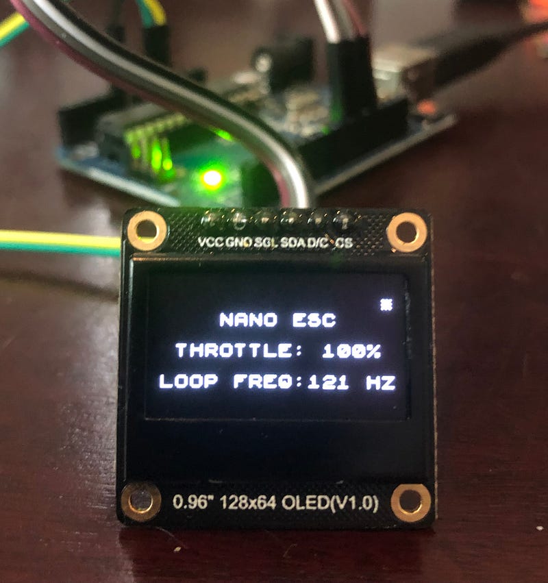
The OLED display that we are testing is the monochrome 0.96” OLED display from DFRobot called the DFR0650 (Figure 1). This module uses the SSD1306 driver chip, has 128 x 64 self-illuminating white pixels, and can communicate with the MCU using I2C or SPI. The module can be powered from 5V or 3.3V and the I2C address is 0x3C. There are many other similar displays in the market and this is not a DFRobot design issue.
2.0 I2C Vs SPI
I2C is the default communication protocol for the display and only requires connecting two pins (SCL and SDA) in addition to power. However, it is slower than SPI. The I2C protocol defines the following data rates: 100 kbit/s (clock 100 kHz — Standard Mode), 400 kbit/s (clock 400 kHz — Fast Mode), 1 Mbit/s (clock 1 MHz — Fast Mode Plus) and 3.4 Mbit/s (clock 3.4 MHz — High Speed Mode). Not all of these are available on the UNO.
The ATmega328P in the UNO provides an I2C serial interface via the 2-wire Serial Interface (TWI ) module (Figure 2). The MCU permits data transfer speeds up to 400 kHz via the Bit Rate Generator.
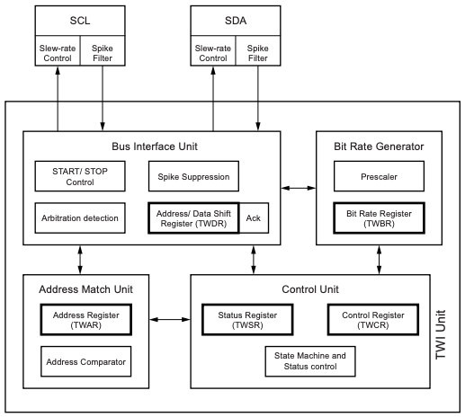
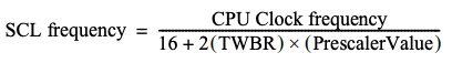
The SCL period is controlled by settings in the TWI Bit Rate Register (TWBR) and the Prescaler bits in the TWI Status Register (TWSR).
Normally with an Arduino you will be using the Wire library for I2C communication which sets the data transfer clock speed to 100 kHz when you call Wire.begin(). To set it to the maximum available speed on an UNO use:
Wire.begin();
Wire.setClock(400000UL);
Alternatively, you can set the register value directly using the formula above. The UNO clock frequency is 16 MHz, the default prescaler is 1 and the default value for TWBR is 72 on the UNO (SCL Frequency = 16000000 / 16 + 2 x 72 = 100 kHz). Changing TWBR to 12 will result in a SCL frequency of 400 kHz.
Wire.begin();
TWBR = 12;
Let’s compare that 400 kHz with SPI. The default SPI data transfer rate on the UNO is 1/4 of the system clock (i.e., 4 MHz). The maximum SPI speed is half the system clock (i.e., 8 MHz). So maximum SPI on the UNO is 20 times faster than maximum I2C. In their default configurations it is even worse, SPI is 40 times faster than I2C.
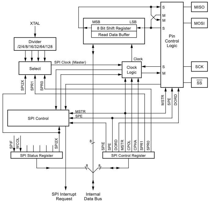
To set the SPI clock speed you would normally use SPISettings(speed, dataOrder, spiMode) and pass this into the SPI.beginTransaction() function. SPISettings has three parameters:
- speed: 8000000, 4000000, 2000000 or 1000000 Hz. Speed of communication. The Arduino board will automatically use the best speed that is equal to or less than the number you use with SPISettings.
- dataOrder: MSBFIRST or LSBFIRST. Is data shifted in Most Significant Bit (MSB) or Least Significant Bit (LSB) first? Most SPI chips use MSB first data order.
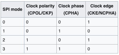
- spiMode: SPI_MODE0, SPI_MODE1, SPI_MODE2, SPI_MODE3 — SPI mode number (refer to Figure 4).
In our application we are not controlling SPI directly but it is used by the u8g2 library.
3.0 U8g2 Library
U8g2 is a monochrome graphics library for embedded devices. U8g2 supports monochrome OLEDs and LCDs, which use the SSD1306 driver (amongst others). From the data sheet, the SSD1306 has a maximum clock period of 100 ns which equates to 10 MHz for 3 and 4 wire SPI, so the limiting factor is the maximum UNO/Nano SPI speed of 8 MHz. U8g2 will try to assign the best bus clock for the current display, but to check that we can use the setBusClock(uint32_t clock_speed) function. This command must be placed before the first call to u8g2.begin() or u8g2.initDisplay().
u8g2.setBusClock(8000000);
u8g2.begin();
Setting the bus clock to 8 MHz had no effect on the loop frequency, so it appears that it has already been optimised. Note that the OLED display uses 16 grey levels represented by 4 bits for each pixel. Thus each pixel requires 4 bits to be transferred when we refresh the display. With a 128 x 64 pixel display this is 32,768 bits or 4096 bytes.
U8g2 supports three different drawing modes:
- Full screen buffer mode — fast, all graphics procedures can be used, but requires a lot of RAM. The constructor must include the “F” character. For example:
U8G2_ST7920_128X64_F_SW_SPI(rotation, clock, data, cs [, reset]) - Page mode (This is the U8glib picture loop) — all graphics procedures can be used, a small amount of RAM is required, but slow. The constructor must include the “1” or “2” character. For example:
U8G2_ST7920_128X64_1_SW_SPI(rotation, clock, data, cs [, reset]) - U8x8, character only mode — fast, no RAM required, no graphics possible, and not available for all displays. Use the U8x8 constructor from here. For example:
U8X8_ST7565_EA_DOGM128_4W_SW_SPI u8x8(clock, data, cs, dc [, reset])
The drawing mode is set when you instantiate a new u8g2 object. The examples provided by DFRobot for their OLED display are:
- I2C —
U8G2_SSD1306_128X64_NONAME_F_HW_I2C u8g2(/* rotation=*/U8G2_R0, /* reset=*/ U8X8_PIN_NONE); - SPI —
U8G2_SSD1306_128X64_NONAME_1_4W_HW_SPI u8g2(/* rotation=*/U8G2_R0, /* cs=*/ 10, /* dc=*/ 9);
The 15 Hz cycle time we measured (Figure 1) is using page mode and four-wire hardware SPI. The test sketch that we used was derived from the examples found in the u8g2 library.
We don’t need to draw graphics and character only mode (U8x8) should be the fastest option and doesn’t require RAM, so we decided to test that and measure the results.
The available constructors can be found in the u8g2 Github repository. We need ones that include the SSD1306 driver and 128 x 64 pixels (Figure 6).
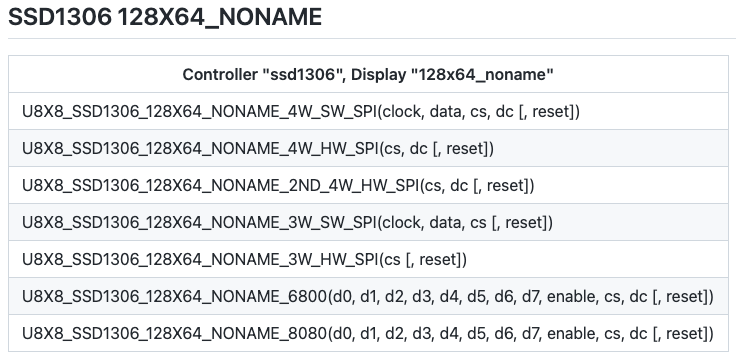
There are two 4-wire hardware SPI options in Figure 6, and we tried them both. The first one (U8X8_SSD1306_128X64_NONAME_4W_HW_SPI) was a significant speed increase, with a loop cycle frequency of 120 Hz (Figure 5). The 2nd constructor (U8X8_SSD1306_128X64_NONAME_2ND_4W_HW_SPI) didn’t work with the DFRobot display. The code used for testing the U8x8 library is shown below.
Note that the U8x8 and U8g2 API’s are quite different, not only in the function names but in how they operate.
4.0 Hardware SPI vs Software SPI
To operate the OLED display using 4-wire SPI, we need to connect 6 pins, and planned on using VCC (5 V), GND, MOSI (D11), D/C (D12 — this is a problem), SCK (D13) and CS (A0/D14).
Due to a shortage of pins we were trying to use the MISO (D12) pin for D/C and one of the analogue inputs (A0/D14) for CS. This did not work for hardware SPI. Using A0 for CS is ok, the problem is D12. When hardware SPI is enabled on the ATMega328P, the data direction of the MOSI, MISO, SCK, and CS pins are overridden according to the table in Figure 5.
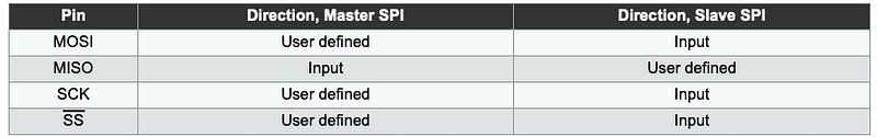
In the ATMega328P data sheet, CS is called SS (Slave Select) and the bar on top indicates that it is ACTIVE LOW. Note that even if you’re not using the SS pin, it must remain set as an output; otherwise, the SPI interface can be put into slave mode, rendering the library inoperative. We are using D10 (CS) for PWM, but as long as CS is configured as an output, the pin can be used as a general output pin which does not affect the SPI system.
Looking at this table, MISO or D12 is forced to be an input and we were trying to use it as an output. So even though our OLED device isn’t using MISO, we can’t use that pin as D/C.
We do have D0 (Rx) and D1 (Tx) spare and if necessary we could add a switch on the PCB to disconnect these pins while uploading a program or using the serial monitor. To try and avoid that we will see how “quick” software SPI is. The hardware versions of I2C and SPI should be faster than software emulation, but there is only one way to know for sure!
To use software SPI instead of hardware, we changed the constructor in the code block above to:
U8X8_SSD1306_128X64_NONAME_4W_SW_SPI u8x8(SCK, MOSI, CS, DC);Using software SPI, the loop cycle time increased to 780 Hz! We were not expecting that. This was so unexpected we raised the issue in the Arduino forum. There were a number of responses, with everyone in furious agreement that software SPI should be slower than the hardware equivalent. The author of the U8x8 library did their own tests using an UNO and measured:
- HW SPI: 2444 Hz
- SW SPI: 1638 Hz
We are not sure why we are getting different results but the actual hardware that we are using is a Nano and we will retest when we have the PCB assembled.
5.0 The SSD1306Ascii Library
Another option is the SSD1306Ascii library. SSD1306Ascii is an unbuffered character only library for small OLED displays like the Adafruit 1.3" and 0.96" monochrome displays. It runs on Arduino AVR boards, Arduino Due and many other Arduino style boards that have the SPI or Wire (I2C) library.
The SSD1306Ascii library works a bit differently to the u8g2 one, instead of specifying a co-ordinate or row/column to print at, you just send a print() or println() command like you would do for the serial monitor.
Comparing software SPI rates, this library delivered a loop frequency of 25 Hz. However, there is a trick you can use to speed things up. If you use oled.SSD1306Ascii::setCursor(0,0) instead of oled.clear() in the printing loop, then the frequency increases to 100 Hz.
6.0 Conclusion
Based on our limited tests, the u8x8 library in SPI mode appears to be the fastest option with the added benefit of not using much RAM. There are a few other libraries that we haven’t tested, including:
- The lexus2k ssd1306 Library — Supports color, monochrome OLED displays, and VGA monitor. This library only has hardware SPI available which would require a change to our PCB. We may revisit this option if we need to update the PCB for some other reason, but the library does seem to be targeting graphics rather than characters.
- The Adafruit_SSD1306 Library — Adafruit library for Monochrome OLEDs based on SSD1306 drivers. This library also requires the Adafruit GFX library, which provides graphics primitives such as lines, circles, text, etc. This library has the option of software SPI, but is a bit more heavyweight than the u8x8 option.
We would be interested if anyone had an option that we haven’t considered. Let us know in the comments. This article came about due to a project that we are working on, an Arduino Nano based Electronic Speed Controller. If you are interested in how this issue evolves than keep an eye out for that series. Part 2 is out now!
If you enjoyed this article and would like to help support my writing, then please subscribe to become a Medium Member. I will get a portion of your subscription fee and you get access to every story on Medium. Alternatively, you can buy me a coffee!
[1]: Ref: ATMega328P Data Sheet — https://ww1.microchip.com/downloads/en/DeviceDoc/Atmel-7810-Automotive-Microcontrollers-ATmega328P_Datasheet.pdf
[2]: Ref: Wikipedia Serial Peripheral Interface — https://en.wikipedia.org/wiki/Serial_Peripheral_Interface
[3]: Ref: U8x8 Constructor Prototypes — https://github.com/olikraus/u8g2/wiki/u8x8setupcpp#ssd1306-128x64_noname


