
Building Memory With Logic Gates
Introduction
In a previous post, I discussed how computers built initially did math using logic gates. I also went over how you could replicate this with code in JavaScript.
I am going to attempt to do something much more ambitious in this post. I am going to attempt to replicate RAM in a similar fashion.
Holding State
In the previous post, we discussed binary numbers and how the presence or absence of electricity in a circuit can be modeled as a 0 or a 1 respectively.
However, a fundamental problem with electrical circuits is that they are transient. They can’t hold state of their own. For example, from one second to the next, a wire has no idea whether electricity passed through it in the second prior.
Let’s fix that problem with some logic gates. I’ll show you three different images showing different variations of the same circuit.

The two logic gates being used in the above set of images are NOR gates. Here is the truth table for a NOR gate.
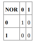
Let’s look at image one first. The NOR gate on the left has an output of 1 because both its inputs are 0 initially.
If you close the gate on top, the output of the NOR gate on the right becomes 1 because both its inputs are now 0 and the bulb lights up.
Here’s the crazy bit(no pun intended): if you now open the gate on top, the bulb still remains lit!
Why? Because both the inputs to the NOR gate on the right are still 0, so the output remains 1. We just created memory in a circuit!
Now, no matter how many times you open or close the gate on top, the bulb will remain lit. The only way to turn the bulb off is to close the bottom gate while keeping the top gate open.
This circuit is typically called a flip-flop circuit. The circuit illustrated here is more commonly called a Reset-Set flip-flop (R-S flip flop). Here is another way to draw the circuit. The circuit remains the same, just with the light bulb removed and two outputs being shown, one for each NOR gate.
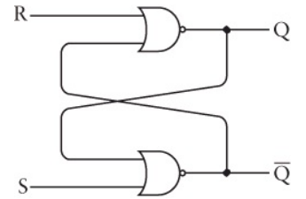
Here is the truth table for the same:
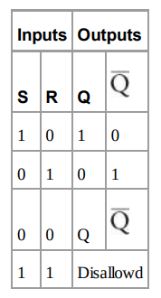
However, the R-S flip flop has an issue associated with it. If you look at the truth table, you’ll notice that if both the inputs are set to 1, the output is indeterminate.
To avoid this, we will use something called a level-triggered D-type latch. Here is the schematic.

Notice that the right half of the diagram is the exact same as our original R-S flip flop. The left half has two additional AND gates connected to two inputs called the Data input and the Clock input.
The Data input can never provide the same input to both AND gates because it is connected to an inverter. The Clock input typically alternates between 0 and 1, and it serves to determine whether the current data input needs to be remembered or not.
Inputs OutputsD Clock Q Q_bar0 1 0 1
1 1 1 0
X 0 Q Q_barThere is a difference between having a Clock input of 0 or 1. When the Clock input is 1, the outputs Q and Q_bar reflect the identity and inverse of D respectively. When the Clock input is 0, the input D does not matter and the outputs remain the same.
Let’s attempt to model the level triggered flip flop in code.
This is an IIFE (immediately invoked function execution). I’m using this to maintain an internal state for a function without exposing it to the global scope. You can read more about IIFE’s here.
The flipflop function expects a data and a write parameter. The state is only overwritten if write is 1. Great, we’ve figured out a way to store a bit!
You can run the above code with functions like below:
levelTrigger.flipflop(0, 1)levelTrigger.flipflop(1, 1)levelTrigger.flipflop(0, 0)var result = levelTrigger.getState()Assembling The Memory
Let’s take the fancy logic gate from the prior figure and represent it as a black box now. We’ll call what we have below a 1-bit latch.
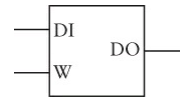
The DO in the above represents the state variable for us.
Now that we can store 1-bit values in a latch, we can store 8-bit values by storing 8 1-bit values in 8 separate latches. The only roadblock is if we have 8 of these latches, how do we differentiate between them?
Simple: we’ll use 3-bit binary numbers. The numbers 0 to 7 represent 8 different values and in binary they go from 000 to 111.
I’m sure you’ve guessed what we’re attempting to do by now. We’re trying to represent each of these functions in memory with the 3-bit binary number representing the memory address. (This is, obviously, a very simplistic model).
Unfortunately, JavaScript doesn’t allow memory access unlike C. For example, in C, you could get access to the address of a function pointer like so:
With JavaScript we’re going to fudge it a little bit. We’ll use a plain JS object to represent our internal memory. Not a bad approximation at all.
I’ve built upon the code we had initially, just replacing the internal state variable with a memoryObj
This is the logic circuit representation of what we’ve built so far.
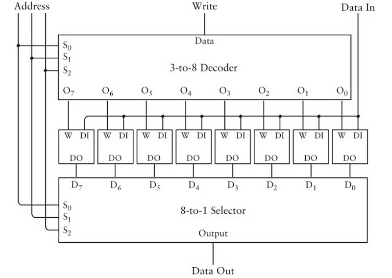
It may seem like a massive jump, but look carefully at what the circuit does. There are 8 1-bit latches in the middle and there is a write signal and a data in signal being provided. The address is the 3-bit address representing each of the 8 latches.
The 3-to-8 decoder and 8-to-1 selector are complex logic gates that perform the functionality of targeting specific memory addresses based on the address signal being fed in to them. Something we easily accomplish in a programming language like JavaScript with the key-value pairs of an object.
If you want to understand what the 3-to-8 decoder and 8-to-1 selector do, read here and here. I’m going to skip over it because for our purposes, it is enough to understand that these are circuits through which we feed electric signals to map to a specific memory address.
The Size Of Memory
Let’s think about how much memory we have based on our previous example so far. We have the ability to store 8 1-bit values to give us a total of 8 bits.
What we built above is typically called an 8x1 RAM array. The reason we are limited to 8 bits is because we used a three bit memory address.
Since 2³ = 8, we have the general formula of:
2^n = Total Number Of Bits That Can Be Stored, where n = the number of bits in the memory address.
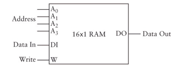
If we have a four bit memory address where each address can store 1 bit, we would have a 16x1 RAM array like below
Now, if we had a 10 bit memory address, we could store 1024 separate bits because 2¹⁰ = 1024.
But, what if we could store more 8 bits in each memory address? Well, then we’d have a 1024 * 8 = 8192 total bits.
If we extend this, we could have a 16 bit memory address with 8 bits stored in each address.
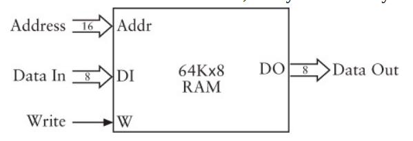
The 64K above actually represents 2¹⁶ = 65,536.
Visualizing Memory
Let’s take a moment to make an approximation of what memory “looks” like in a computer. We know we can reference different addresses in memory using an n-bit number, where n can be any number between and inclusive of 1 and 16.
If we were to physically represent this, it might look something like this:
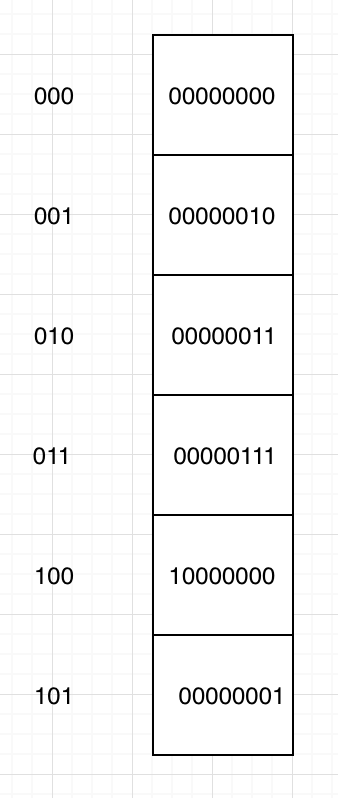
Each of the blocks in the column on the right represent a separate piece of memory. Each piece of memory is composed of 8 1-bit latches which we’ve already seen how to construct.
The column on the left represents the 3-bit address of each of the blocks. We can access the 8-bit number by accessing the memory address for that specific number.
Since we are using a JavaScript object to represent our internal memory, we could access the memory like so: memoryObj[address]
Automation
Okay, now that we’ve figured out how memory is built, let’s try to utilize the memory to perform some basic operations. Like addition, for example.
In the binary adder we built in the previous post, we had the ability to add two 8-bit numbers and get the result. Now, what if we want to add a series of 8-bit numbers and get the final result without having to worry about the intermediate result?
We can store every intermediate result in an 8-bit latch and keep updating the running total!
We already designed an 8-bit adder so we can keep feeding the intermediate result and the next number into the 8-bit adder so that we can keep updating the total.
We’ll use the same fullAdder code we developed in the previous post. If you want to just look at the code, you can grab it from my repository. We’ll need to make some adjustments to the levelTrigger function we wrote earlier in this post.
First, the thing to include is an additional function in the returned object from the closure which will allow us to iterate over the memory block. We’ll make this a generator function to allow for intermediate storage of results.
I’ve overwritten parts of the memoryObj with binary numbers represented as a string. We’ll have to convert each of these strings into their integer equivalent before sending them off to be added by the binary adder.
If you noticed, the last key-value pair in the memoryObj is set to null
This is so that we have a place in the memory register to store our sum variable. This is also why we have the check in the generator function for whether the the address we encountered is the very last one in the object. Since we know we are using this address for storing the sum variable, we don’t want to be reading it and adding it to the sum itself!
Now, we’ve made decent progress, but it feels like our automation fell a little short. It seems like all we’ve accomplished is the ability to add numbers in a row and store them in the very last memory address available to us.
Let’s try and fix the lack of flexibility.
Extending Automation
Before we start figuring out how to extend the automation, we are going to make a quick abstraction. I am going to get rid of the levelTrigger we wrote earlier. Instead, we will iterate directly over a JS object or ES6 Map. You can assume that every value within the Object or Map contains a levelTrigger that is capable of maintaining 8-bit state.
The first thing we want to fix is the the lack of ability to do anything other than automation. Here are the operations we’ll try to add: Load, Add, Store and Halt.
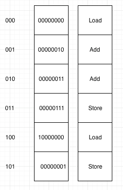
Here is a visual representation of what we’re trying to do.
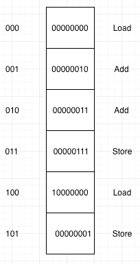
The image is very similar to the one we had previously. We’ve added an instruction for a memory block each, which will tell us what we want to be doing with the data at that specific address.
Load: Load the number at this memory address into the accumulator
Add: Take the number at this memory address and add it to the accumulator total
Store: Save the accumulator total at this memory address
We have two problems to solve if we want to attempt this.
- We have no way of storing this instruction set since the available memory at each block is occupied by the 8-bit number stored there.
- We need to figure out a way to explain the instruction set in binary since that’s the only way to get the computer to understand what we want to do. We haven’t encountered strings yet.
We’ll solve problem 1 first.
We’ve been storing our 8-bit binary numbers in a RAM array. The dimensions of a RAM array can differ as already explained earlier. Why don’t we just use another RAM array to store the instruction set? We’ll store it so that the instruction set corresponds with the memory address we want to perform the operation on.
So, now we have two RAM arrays that correspond at memory addresses with the instruction we want to perform on specific pieces of data. What we would need to do is iterate over both arrays simultaneously, performing the required instruction on each piece of data as we move along it.
Let’s solve the second problem now. I’m going to use a hack to solve this problem because we’re sticking with 8-bit numbers in this post. I’m going to use the largest three binary numbers possible with 8-bits to represent the instruction set of: Load, Add and Store respectively.
Note: This is not how it is done in CODE. By this point in the book, Charles Petzold has introduced the concept of a hexadecimal system. He seems to use hexadecimal numbers to represent the instruction set. I want to avoid bringing up hexadecimal numbers in this post, so I’ll stick to 8-bit binary.
So, here is the instruction set and their corresponding binary representation.
Load: 11111101 (253)
Add: 11111110 (254)
Store: 11111111 (255)
Great! It seems like we’ve solved both our problems. Let’s represent our data and code RAM arrays in JavaScript now.
First, we’re going to get rid of the IIFE’s we had earlier that represented a level triggered latch. I’ll use JavaScript maps to store both RAM arrays. I’m doing this to make the code simpler, and I’m replacing the JS object with a Map because a Map preserves key order.
const dataMap = new Map([["000", "00000001"],["001", "00000001"],["010", "00000001"],["011", "00000001"],["100", "00000001"],["101", "00000001"],["110", "00000111"],["111", "00000001"]]);const codeMap = new Map([["000", "11111101"],["001", "11111110"],["010", "11111110"],["011", "11111110"],["100", "11111111"],["101", "11111101"],["110", "11111110"],["111", "11111111"]]);Now, we can just iterate over the maps for the code and data respectively.
Iterating over a map is easy, you use Map.entries()
We need a way to figure out what to do depending on what instruction set we come across. A simple switch case statement will take care of that.
I’ll show you what I’ve built to explain memory iteration using D3.js in the form of a gif here.
The div on the right represents our accumulator. At memory address 100, we overwrite the data stored with the number from the accumulator because the instruction at that memory address tells us to store the value.
Immediately after that, we run into a load instruction which loads the data at the memory address into the accumulator overwriting the sum stored in the accumulator.
At address 101, we have a Load instruction again, which will overwrite the data in the accumulator with the data stored at address 101.
I’ve hosted the whole code in a Codesandbox here. Feel free to check it out and have a play with the code to see how it works. It’s just plain JS with D3 for the visualization.
Okay, that’s pretty cool! We have the very, very basic beginnings of Assembly.
Conclusion
We’ve seen how to build memory using logic gates, specifically a level-triggered flip flop gate. The next thing we figured out was how the size of memory works, followed by understanding how to address specific memory addresses. We abstracted all of this using a JavaScript object.
Next, we addressed the lack of an instruction set and finally we automated memory to carry out addition, loading and storing of data.
I hope you enjoyed this post, and I will end by highly recommending you grab a copy of CODE to read it.
If you want to follow me, you can do so on GitHub or Twitter. If you have any questions, please don’t hesitate to ask.

This story is published in The Startup, Medium’s largest entrepreneurship publication followed by +399,714 people.
Subscribe to receive our top stories here.


