
How Computers Do Math
To understand the latter half of this article, you will need to know Boolean Algebra. This is not a topic I discuss in this article. Here is a link to where you can learn about it.
Introduction
I’ve been reading Code by Charles Petzold over the past couple of weeks. That book is an absolute goldmine of information.
I’ve been curious to understand how math operations work inside of a computer on a fundamental level. I’ve always been aware that computers carry out mathematical operations differently from human beings because computers operate in binary.
This book answered a lot of questions I’ve had on this topic, and I want to share that information with you.
I’ll be going over how we can do addition and subtraction using logical operators in code. You can replace these logical operators with their logic gate equivalents in the physical world.
This article is an exercise in curiosity, and nothing more. Have fun with it!
Why Binary
First, let’s start with a simple question. Why do we count the way we do? Why do we count 1,2,3,4,5,6,7,8,9,10? Any numbers that come after that are the same with an additional or different digit placed to the left?
Why don’t we count 1,2,3,4,5,6,7,10 for example? It seems a completely arbitrary choice initially.
One possible reason is the number of fingers on our hands.

We have 10 fingers on our hands, so our number system developed the way it did.
Unfortunately, we don’t have the same luxury with electric circuits. Circuits can represent one of two different states at any given time: either the presence or absence of a current running through the wires. So, electrically, we count the following way: 1, 10.
Now, one of the obvious questions here is: Why 1, 10? Why not 1, 2? We need to take a quick diversion to answer that question.
The Importance Of Zero
To understand the importance of zero, let’s compare two different systems of counting. The modern Hindu-Arabic method of counting and the ancient Roman numerals:
Hindu-Arabic: 1, 2, 3, 4, 5, 6, 7, 8, 9, 10
Roman: I, II, III, IV, V, VI, VII, VIII, IX, X
The important difference between the two is the last number. The Roman numeral system has a special signifier for the number 10.
To understand why that’s such a big deal, let’s take a simple example:
Here’s how we write the number 205 in the Roman numeral system:
CCVFor the Hindu-Arabic numerical system, however, we can think of it the following way:
205 = 2 * 100 + 0 * 10 + 5 * 1There is no obvious correlation between the number and the Roman numeral system, whereas there is an obvious correlation between the number 205 and the position of its different digits.
This is the importance of zero. It allows the numerical system to become positional
Still not convinced? Look at the following differences in representation between the Roman and Hindu-Arabic numerical system.
Hindu-Arabic                                 Roman
100                                          C
1000                                         M
It becomes progressively harder to count larger and larger numbers.
You can read more about this here and here
Counting In Binary
Here’s how we count in binary: 00, 01, 10, 11. Each of these digits is called a bit. These are called two-bit binary numbers.
Don’t confuse two-bit with binary. Binary just means either a 0 or 1 in each position. The number of bits dictates the number of digits in each of the numbers.
Now, we need to learn to perform Boolean Algebraic operations on binary numbers. Boolean Algebra is slightly different in its rules, so just follow along.
If you want to understand Boolean Algebra first, here is a nice link that explains everything you will need to proceed.
Below is an image of the result of three different Boolean Algebra operations. These are also called logic gates.
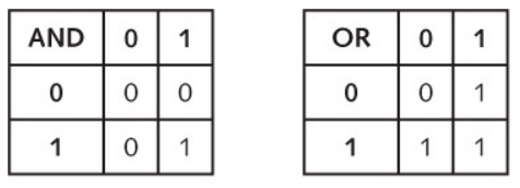
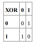
It is possible to build all of the above logic gates using electrical circuits and components. I won’t go into how it’s possible to do that because it will exceed the scope of this blog post. You can, of course, look this up or better yet, buy a copy of CODE and read it!
What we need to know now is how to represent each of these logic gates in code. Here is how we do that in JavaScript.
AND      &
OR       |
XOR      ^
These are called bitwise operators, and I will refer to them as such going forward. If you read bitwise operators, just think logic gates. You can read more about bitwise operators in JS here.
Building A Binary Adding Machine
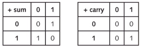
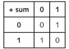
Okay, we have the basic rules for Boolean Algebra. Now, how do we add two binary numbers? Here’s a table for that.
+ 0 10 00 011 01 10We’ll represent the result in 2 bits. The right bit is called the sum bit and the left bit is called the carry bit.
Let’s split the table into two separate ones: one representing the sum bit and one representing the carry bit.
Okay, great! We now know everything we need to add in binary. We need to figure out a way to reflect the two tables above in terms of code.
Combining Circuits And Code
Let’s reiterate what we know now.
- We know three different logic gates and their corresponding operators in JS.
- We know how to add two binary numbers by hand using the sum and carry tables we just discussed.
We need to figure out a way to express 2 in terms of 1. That is how do we add two binary numbers using the different bitwise operators at our disposal.
Let’s replicate the sum and carry tables separately. First, consider the sum table.
Go back and consider the three logic gate tables we have: AND, OR and XOR. If you compare the values of each cell in the sum table and XOR table, you’ll find that they are an exact match.
So, if we have two binary numbers: 0 and 1, doing the following would give us the sum bit. (You can try this out in the dev tools window in your browser).
let a = 0
let b = 1
let result = a ^ b
// result = 1
Next, consider the carry bit. Do the same thing and go back and consider the three logic tables we have and compare them with the carrying table. You’ll find that the carrying table and AND tables are an exact match.
We can express it this way in code
let a = 0
let b = 1
let result = a & b
// result = 0
Okay, great! So we can add two 1-bit binary numbers and obtain the sum bit and the carry bit using a combination of an AND gate and XOR gate. Let’s call this a Half Adder.
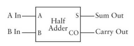
Okay, great! Let’s express this Half Adder in code now.
Here are the numbers we’re going to add: 1010, 0101. In base 10, there will be 10 and 5 respectively.
1 0 1 0
0 1 0 1
-------
1 1 1 1
So, we know how to do that by hand because every column is essentially the same operation: the sum of 1 and 0. We know that it is equal to 1.
Let’s do this in code.
If you run the above code, you should see a result of 15, which is what we expect.
However, there’s a situation we haven’t accounted for yet in the code. If you go back and look at the two binary numbers we added, you’ll notice that we never have any carryover in any of the additions.
What happens if we need to add the following two numbers.
0 0 1 1
1 0 1 1
-------
1 1 1 0
Notice that our code above will fail to provide the correct answer because we never account for the carry over from one column to the next. In fact, even our concept of Half Adder fails to account for this because Half Adders only account for two input bits, A and B. We need something that can handle three input bits.
The Full Adder
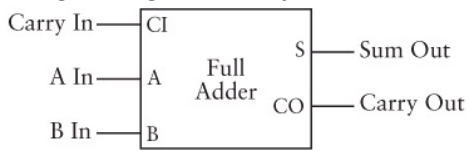
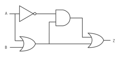
Enter the Full Adder. Under the hood, this is just a combination of two half adders in series with an OR gate. To represent the Full Adder programmatically, we’re going to spend some time investigating it fully.
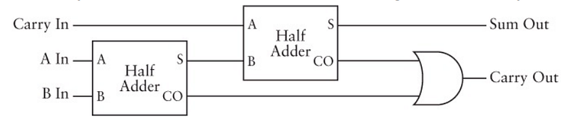
I found it quite difficult to understand how this works. I’ll show you how this works for the second to the right column of the sum we are currently working on, and that should hopefully make sense to you.
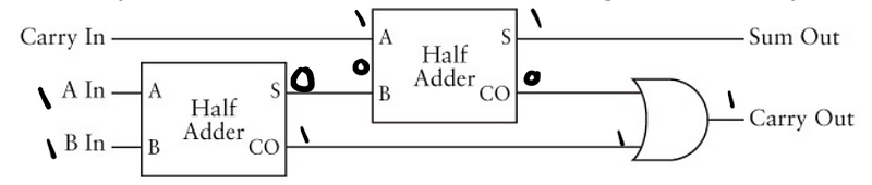
The above image is the annotated version of the second to right column for the following addition.
0 0 1 1
1 0 1 1
-------
1 1 1 0
The two inputs to the first half-adder in the circuit are the two values in the columns, which are 1 and 1.
The inputs to the second half-adder in the circuit are the sum of the previous half-adder and the carry over from the column on the right.
The carryover from the current column and the carry over from the column on the right are both fed into an OR gate next. The result of this OR computation is the carryover from this column to the column on the left.
Why do we have that OR gate at the end though? Why don’t we have another half-adder there? Well, we could, but an OR gate is far simpler. The reason the OR gate works is that there is no set of possible inputs to the first two half-adders that would result in two 1’s as inputs to the OR gate. You can go ahead and try out a set of inputs and test it for yourself.
Let’s represent the Full Adder in code now.
You will notice a few differences in the way I’ve structured the code for the halfAdder and the fullAdder. The main functional difference is the variable that is constantly overwritten with the carrying out from the previous column.
Also, at the end of the reduction, I check if carryIn === 1 to make sure that I don’t miss out the carry over from the column on the extreme left.
I’ve also added in a little helper function called convert2Decimal so we can see the result in base 10.
If you want to think about it physically, here is what we’ve managed to build so far.
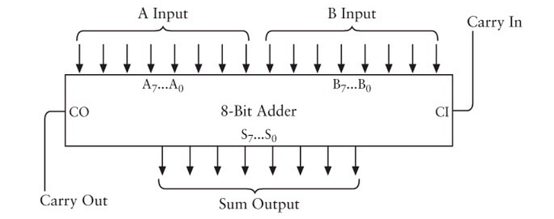
The computation of each column requires a full adder. Therefore, our 8-bit adder is composed of 8 Full Adders. The carry out from each one serves as the carry in for the subsequent one.
The sum bit from each column is carried out and aggregated to provide the 8-bit sum output.
Building A Binary Subtraction Machine
Note: The Binary Subtraction Machine we build in code is going to have two important limitations: 1. It will only be able to handle 8-bit numbers 2. It can only subtract numbers with a positive result. These limitations are introduced to reduce the complexity of the problem
Okay, now that we’ve covered how to do binary addition via code, let’s turn our attention to binary subtraction. We’ll be building subtraction as an abstraction onto the 8-bit adder we’ve built in the previous section.
First, we’ll look at the way we normally do subtraction by hand.
 253      Minuend
-176      Subtrahend
----
 077      Result
You’ll notice some nomenclature above regarding the values. Just remember what it’s called. Now to perform the above subtraction we need to borrow from numbers on the left. This is tricky to pull off in binary numbers. Here’s a little math trick illustrated in Code instead.
   253 - 176
=  253 - 176 + 1000 - 1000           // add and subtract 1000
=  253 - 176 + 999 + 1 - 1000        // split 1000 into 999 + 1
=  253 + (999 - 176) + 1 - 1000      // rearrange the numbers
=  77
The beauty of this trick is that there is no longer any borrowing involved for any of the operations. Test it out for yourself and see.
The most important part of the above steps is the
999 — 176
The result of this is called the 9’s complement of 176.
In binary terms, this would be called 1’s complement and be represented as the following (here, you subtract the binary representation from 255, which is the largest number possible with 8 bits):
  255 - 176
= 11111111 - 10110000
= 01001111
If you look carefully at the binary number on the R.H.S of the subtraction and the result of the subtraction, you will see the result is the exact opposite of the R.H.S (where there was a 1, now there is a 0 and vice versa).
A quick way to simulate this in JavaScript is the ~ operator. But, there is a problem with JavaScript’s representation of positive and negative binary numbers.
JavaScript represents all numbers only as floating points. Internally, it converts these numbers to integers, performs calculations on them, and then converts them back. JavaScript uses both signed and unsigned integers for representation internally (source).
If we want to use the ~ operator, we want to deal only with unsigned integers.
Note: If you want to learn more about this issue, I recommend reading these answers on SO linked here and here
Since JavaScript is a loosely typed language, we can coerce the signed integer into an unsigned integer, and then deal with it. The operator we will use is the >>> operator (docs here).
Let’s make a small addition to the convert2Binary function that we used earlier.
function convert2Binary(num, padding) {
  return ('00000000' + (num >>> 0).toString(2)).substr(-padding)
}
We made two additions to the function:
- We added an extra parameter called padding. This is so we can control the number of digits we will be using when we convert to binary. This is so that we can temporarily handle the number 256 as an intermediate step.
- We’re coercing the
numparameter before converting it to binary.
Let’s take a look at the operations we’re trying to perform again
253 + (999 - 176) + 1 - 1000 | a |
| b |
| c |
| d |The vertical lines represent the boundaries of each of these steps. For example, step a operates only on the numbers within the parentheses and so on. This order of operations is the one I’ve followed in my code. Here is the code for the subtract function
There is very simplistic error handling at the beginning of the function. Also, when I pass in the number 256 to the convert2Binary function, I pass in a padding of 9. This is because 255 is the largest number you can represent with 8 bits, so now we need 9 bits.
We have one more step to cover. Step d requires that we carry out a subtraction. How do we carry out this subtraction?
Let’s think back to the logic gates. What logic gate simulates the subtraction operation?
The XOR gate provides us with exactly what we need. Since the only subtraction we’re carrying out is between 256 (binary representation: 100000000) and a number lesser than 256, we never need to worry about borrowing. Here is the code for what we will call the fullSubtractor
Also, we’re going to update the binaryAdder function we developed in the previous section. Since, we want the ability to perform either addition or subtraction using the same 8-bit adder we developed previously, we’ll need to add something to differentiate between when we want to do addition or subtraction. We’ll use a number as a parameter for this. 0 will mean addition (which will be the default), and 1 will be subtraction.
Finally, here is the code in its entirety.
Here is what we’ve managed to build a representation of in code. It is not a perfect representation but it performs almost the same functionality, in the same manner.
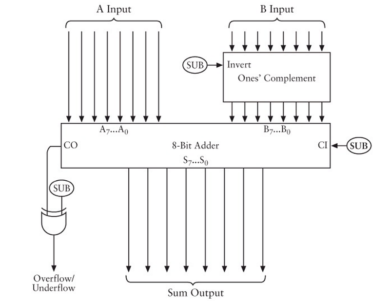
Notice that the input of B, goes through One’s Complement box that is fed a SUB signal. The SUB signal is either a 0 or a 1. If it’s a 0, the B input is not inverted and vice versa. We simulated this using the operationBit parameter we passed into the binaryAdder function.
Conclusion
There you have it! We just figured out how to represent a binary adder in code. Our binary adder can perform addition and subtraction of numbers by simulating logic gates. There are, of course, a vast number of simplifications.
I am currently trying to figure out how to represent multiplication and division using logic gates. It is vastly more complex but an interesting exercise nevertheless.
Finally, I can’t recommend reading CODE by Charles Petzold enough. I’ll leave you with a review I read on the back of the book that I think described it perfectly.
“You can tell writing CODE was a labor of love for Petzold, and reading it is too” - Bill Camarda, Editor, barnesandnoble.com

This story is published in The Startup, Medium’s largest entrepreneurship publication followed by +389,305 people.
Subscribe to receive our top stories here.


