
Visual Perception GUI
A user interface implemented with QT Creator, Opencv, and C++ to make the user able for realizing what they learned during this tutorial like Camera Calibration, Fundamental-Essential Matrix Estimation, Triangulation
The GUI consists of 3 parts as Calibration, Feature Matching, and Epipolar Geometry.
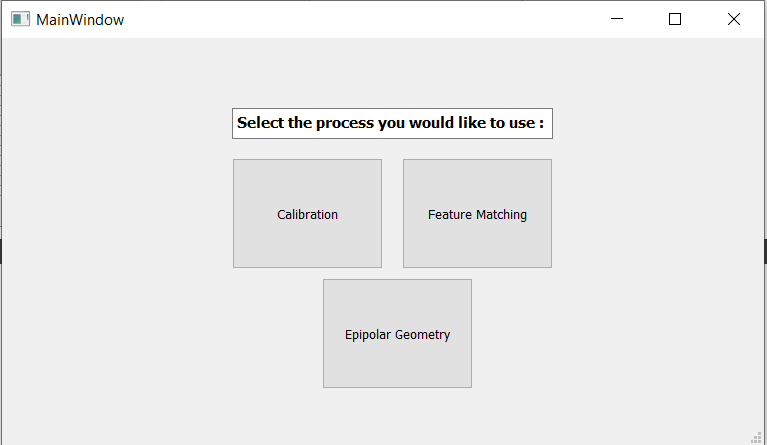
Let’s examine it part by part
Calibration
In this part, you can calibrate your camera either using your already taken images or using your camera connected to your PC. Additionally, there is a Demo section for you to start trying more easily.
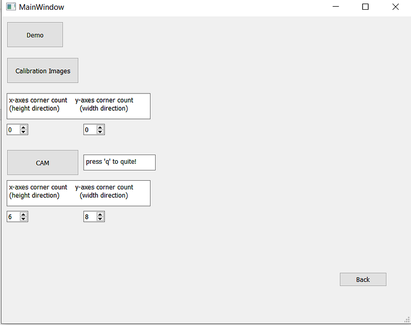
o Demo
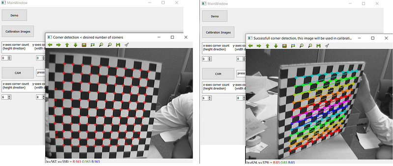
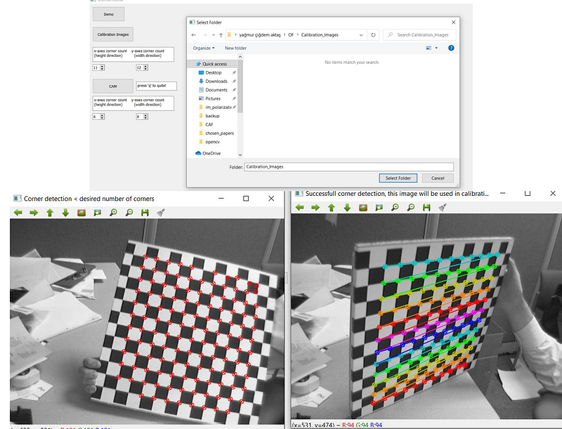
By clicking the Demo button, the user can use default checkerboard pattern images to see how it is working. Each image with corner detections drawn on them is showing. If the expected number of corners can be detected, it is a successful detection. These type of images are shown with the message “Successful corner detection, this image will be used in calibration” and if less than expected corners are detected, the image is shown with a message “Corner detection < expected number of corners”.
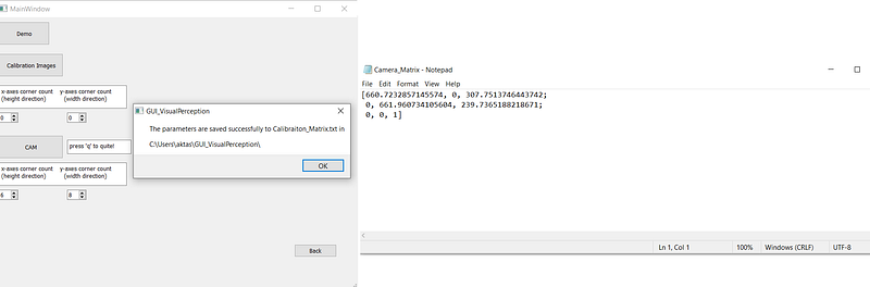
Afterward, only the successful images are used for calibration and we get another message if calibration is done without any problem. The message shows the directory where the calibration results are saved in a file. By looking at the mentioned file, we see the following result:
o Calibration Images
By clicking this button, the user can select the folder where his own calibration images are. Before selecting this folder, the user should correctly determine the number of corners to detect in the x and y axes. After that, the calibration process will start automatically.
I determine the number of corners then select the folder where my calibration images are and we see the same process works.
o CAM
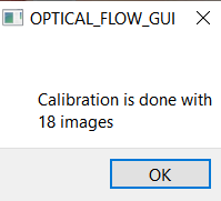
It is also possible to calibrate cameras via webcam. The user can click on CAM button right after determining expected corner counts and show the checkerboard images to the camera. The same process will work. To quit, the user should press ‘q’. For the CAM option, there is only an additional message is sent to the interface to declare how many images are used for the calibration. For how many images, corner detection was successful. Because it can get a little confusing to see if the image were good or not trying to show the checker pattern to thE camera. The further process is the same:
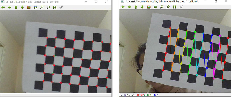
For the CAM option, there is only an additional message is sent to the interface to declare how many images are used for the calibration. For how many images, corner detection was successful. Because it can get a little confusing to see if the image were good or not trying to show the checker pattern to the camera. The further process is the same:
Measures Taken for This Section
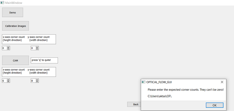
- If the user forgets to determine the corner the calibration will fail. So instead of opening a file explorer, a warning message is sent.
2. The calibration may not be successful every time. Two main reasons for that are not having enough successful images. Either the expected corner quantity is given wrong or there is a small number of images. For example, the user may press ‘q’ too early in the CAM case. In that case, to warn the user that the calibration is not performed, a message is sent.
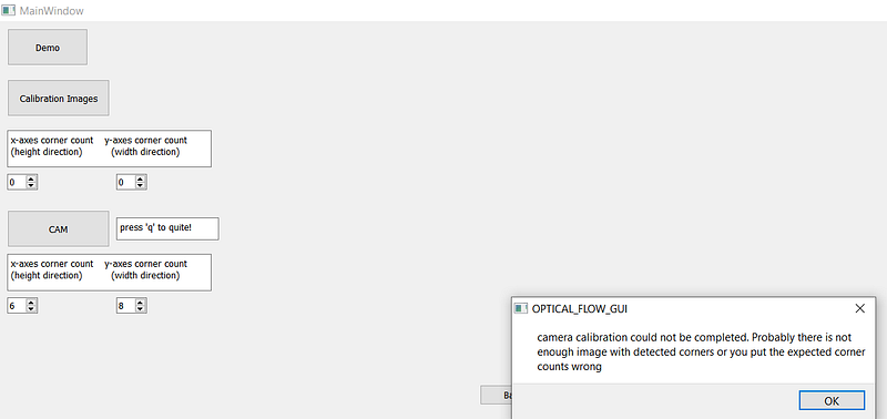
3) These problems cause run time errors so they are cached in the background too.
Feature Matching
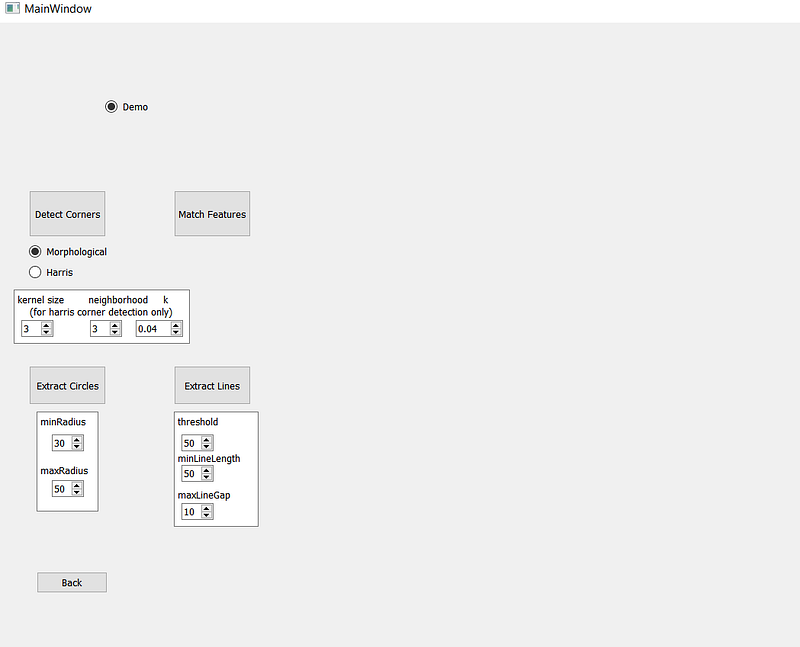
If the Demo box is checked, the process will be done with default images. If not, to detect corners, extract circles and extract lines, 1 image will be required. For match features, 2 images will be required. In case any image didn’t select, a warning image is sent, in case only 1 image is selected for Match Features, the same image will be used as left and right images.
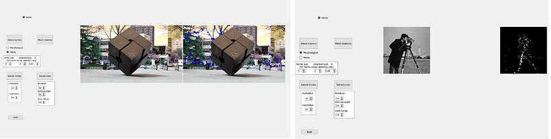
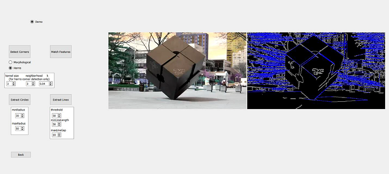
o Detect Corners
Harris Corner or Morphological operators can be selected for that process. For Harris Corner, the user can define kernel size, neighborhood, and k. We see demo image results for both:
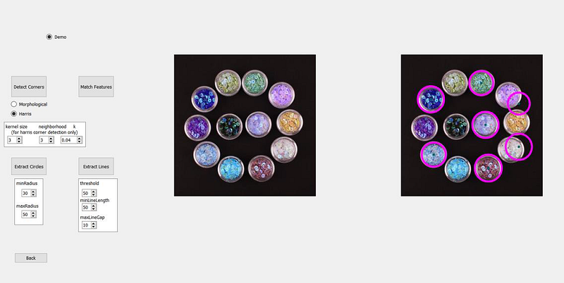
o Extract Circles
For extract circles, the user can define the minimum and the maximum radius of circles. Any circle being outside of this range won’t be extracted. We see demo image results.
o Extract Lines
The user can define a threshold, minimum line length, and maximum line gap.
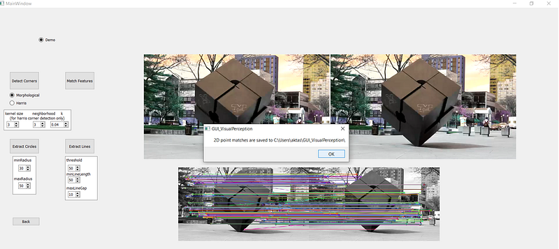
o Match Features
This is the part we need mostly for going further for Epipolar Geometry. As I mentioned in the previous post, we need to have 2D matched image points to obtain Essential Matrix, Fundamental Matrix, Triangulation, etc and in real-life examples, we usually don't have them in contrary that we used already matched points to be able to continue more easily during the tutorial. By clicking this button, you can obtain the matched points as Matched_Points1.txt and Matched_Points2.txt. The epipolar geometry part expects .txt files for 2D points, so you can directly use what you obtained from that section.
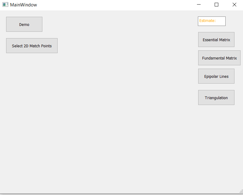
Epipolar Geometry
In this part, you will be able to work with everything we learned in Epipolar Geometry post.
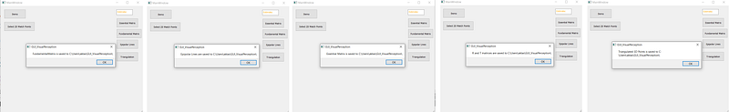
By clicking the Demo button, the 2D matched points coming from Match Features Demo images are used and you will see that various tasks are realized step by step. At the end of each step, a message is sent to the user to inform where the output matrix or vector was saved.
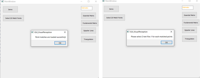
To work with your own matched points, you should select 2 different files, 1 for the 2D points that comes from the first image, 1 for the 2D points comes from the second image as a txt file. If you obtained your points using this GUI, you already have them as .txt files and you can keep working with them without the need for any conversion operation.
After choosing your files, you will see this information message “Point matches are loaded successfully!”, but if you select less or more than 2 files, you will get a warning message and you need to click again to Select 2D Match Points.
Then you can try Essential Matrix, Fundamental Matrix, Epipolar Lines and Triangulation buttons! For each step, you will get a message if you need to select anything and a message to inform you where your results are saved if everything went fine.
Don’t forget that for example, Essential Matrix requires Camera Matrix, and if you don’t have it yet, you can go to the Calibration section and obtain your Camera Matrix before estimating Essential Matrix!
You can find the source code via this Github link.
Please don’t forget to change these dependencies according to your path in GUI_VisualPerception.pro file.
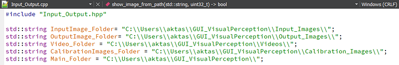
and these absolute paths in the Input_Output.hpp file!
Thank you for your interest and have fun with GUI!
[1] https://ros-developer.com/2018/12/19/creating-a-simulated-stereo-vision-cameras-with-opencv-and-c/
[2] https://docs.opencv.org/3.4.15/d9/d0c/group__calib3d.html#ga19e3401c94c44b47c229be6e51d158b7