
Transistors: The Binary Magic
How we observe it on our devices’ screens

“The screen is a magic medium. It has such power that it can retain interest as it conveys emotions and moods that no other art form can hope to tackle.”
― Stanley Kubrick
Ever wondered how all the magic you see on a smartphone’s screen is being generated? Or even being more specific, how these three words have been displayed on the screen? Interesting, no? Let me show you how it’s done!
This article is the second article in a series of three articles:
⚫ Transistors: The Greatest Invention of the 20th Century.
⚫ Transistors: The Binary Magic.
⚫ Transistors: Let’s Time-Travel Together.
In case you haven’t read my first article, Transistors: The Greatest Invention of the 20th Century., it is highly recommended to read it in case you want to complete the whole puzzle.
Let’s dive in.
The binary language
“There are 10 kinds of people in the world: those who understand binary numerals, and those who don’t.”
— Ian Stewart
What do you think of the quote above? If you think it’s okay, you know something about the binary language, and you can skip to the next part; otherwise, you might want to read on — just in case you want to know what the “binary language” is all about.
Imagine you had a keyboard with only two buttons: button-0 and button-1, and you wanted to represent the numbers ‘0’, ‘1’, and ‘2.’
‘0’ would be the easiest to represent by simply pressing the button-0.
‘1’ would be very simple as well. All you need to do is press button-1.
‘2’ is not straightforward; you’d have many options, but let’s concentrate on the following two options:
Press button-1 — for each ‘1’
This option would mean that if you want to represent the number ‘1’, you will press button-1 once, twice for ‘2’, three times for ‘3’, and so on.
That would also mean you need to press the button-1 15 times to represent the number ‘15’. That would be arduous, don’t you think?!
Let’s see if there is another way to represent the numerals, not particularly straightforward but achievable with less button pressing.
Decide what button to press — for each division on 2
It might sound awkward at first. But still, once you get used to the concept, it gets easier.
Imagine you would follow this simple algorithm every time you need to represent a number.
- If the number is bigger than 0, press button-1; otherwise, press button-0.
- While the number can be divided by 2, press button-1 only if the remainder is 1; if the remainder is 0, press button-0.
That’s all! Now let me explain.
Let’s start with ‘0’.
- If the number is bigger than 0, press button-1; otherwise, press button-0. — button-0 is pressed.
- While the number can be divided by 2, press button-1 only if the remainder is 1; if the remainder is 0, press button-0. — No, it can’t be divided by 2.
The numeric result is ‘0’.
Now let’s do ‘1’.
For ‘1’, it’s uncomplicated,
- If the number is bigger than 0, press button-1; otherwise, press button-0. — button-1 is pressed.
- While the number can be divided by 2, press button-1 only if the remainder is 1; if the remainder is 0, press button-0. — No, it can’t be divided by 2.
The numeric result is ‘1’.
Now let’s do ‘2’.
For ‘2’ it’s simple also,
- If the number is bigger than 0, press button-1; otherwise, press button-0. — button-1 is pressed.
- While the number can be divided by 2, press button-1 only if the remainder is 1; if the remainder is 0, press button-0. YES can be divided by 2; since the remainder is 0, button-0 is pressed.
The numeric result is ‘10’.
And finally, let’s do ‘3’.
For ‘3’, it’s straightforward as well,
- If the number is bigger than 0, press button-1; otherwise, press button-0. — button-1 is pressed.
- While the number can be divided by 2, press button-1 only if the remainder is 1; if the remainder is 0, press button-0. YES can be divided by 2; since the remainder is 1, button-1 is pressed.
The numeric result is ‘11’.
Following this approach, how many times would you press a button to represent the number ‘15’? Try it yourself.
The answer is 4 times.
The numeric result should be ‘1111’.
This was briefly the binary way of counting, so now we agree that there are ‘10’ types of people, those who understood my explanation and those who did not. Well, I really hope you all did!
To conclude, in case you have read my previous article Transistors: The Greatest Invention of the 20th Century, then you can clearly see that this keyboard, can in a very intuitive manner, be replaced with a transistor, and as simple as that, we have built a control unit that can generate binary numerals.
In order to use these binary numerals, to generate Numbers, Letters, and Colors, we need a binary logic.
The binary logic
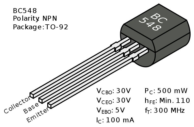
Let’s recall the transistor from my previous article Transistors: The Greatest Invention of the 20th Century:
In case you remember, without any voltage applied to the base(see figure below), the transistor will act as an insulator — outputting 0.
However, applying a positive voltage to the base would turn the transistor into a conductor — outputting 1.
Let’s introduce a few terms first.
Given a transistor:
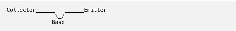
Then by changing the names of Base to Input and Emitter to Output, we get:
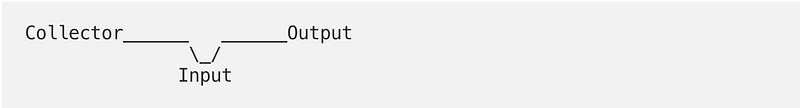
What is a logic table? A logic table is a simple table that shows input/output using binary digits 0 or 1. Here’s an example.
The logic table of the transistor, in this case, is the following:
IN------OUT
0       0
1       1
What is ‘Ground’?

In circuits, the ‘Ground’ symbol indicates the point in the circuit that means “Zero Volts.” i.e., If the current flows to the ‘Ground’ then the ‘Output’ is 0.
What is a logic gate? A logic gate is a composition of a few transistors that will form a gate logic/functionality.
Done with the terms, now let’s see the gates.
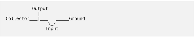
NOT

The logic
Not is an elementary gate that should invert whatever it gets as an input.
The transistors
The NOT Gate is built using a single transistor, and as you can see, if the input is ‘0’, then the output is always ‘1’ since simply the current will flow from the ‘Collector’ to the ‘Output,’ and will not reach the ‘Ground’.
However, if ‘Input’ is 1, then the current will flow to ‘Ground’, and the ‘Output’ in this case will be 0.
The table
IN------OUT
0       1
1       0
AND

The logic
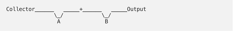
And is a straightforward Gate that would check if both inputs A and B are 1, and only then it outputs a 1, otherwise it outputs a 0.
And as you can see, two transistors are connected in series to form the gate logic. Simply, the two inputs A and B must be 1 in order to have a current flow from ‘Collector’ to ‘Output.’
The transistors
The table
A------B------OUT
0      0      0
0      1      0
1      0      0
1      1      1
OR

The logic
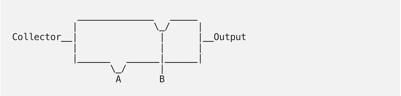
Similar to AND, Or is a straightforward Gate as well, that would check if at least one of the inputs A and B are 1 to outputs a 1, otherwise, it outputs a 0.
And as you can see, two transistors are connected in parallel to form the gate logic. Simply it is enough for one of the Inputs A or B to be 1, in order to have a current flow from ‘Collector’ to ‘Output.’
The transistors
The table
A------B------OR
0      0      0
0      1      1
1      0      1
1      1      1
Using the gates above composed of transistors, we can build more gates, like NAND(The opposite of AND) also XOR(Exclusive OR). Moreover, we can build a Half Adder, and using the half adder; we can build the Full Adder. And finally, using a full adder, it is possible to calculate the addition of two binary numbers.
For example:
110 (equals 6 in dicimal)
+
011 (equals 3 in dicimal)
_________________________
1001 (equals 9 in dicimal)
Using the adders, we can build arithmetic logic units or ALUs to perform arithmetic and bitwise operations on binary numbers. And with an ALU, we are ready for the magic to happen.
The magic
Is it possible to generate numbers, letters, and colors using only two digits, 0 and 1? Yes, it’s possible! Let me show you how it’s done!
Numbers
As we have already seen, numbers can be translated from decimal to binary, and vice versa, e.g., ‘5’ in decimal is ‘101’ in binary. Using the ALU, various arithmetic and bitwise operations can be performed, Like add, subtract, etc.
Letters
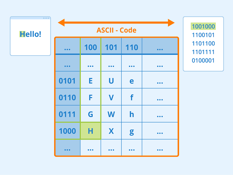
ASCII stands for “American Standard Code for Information Interchange” and describes a standard for text data and information exchange.
As you can see, each letter has a binary representation, and if we get back to “these three words,” I mentioned in the beginning. Then, by finding the representation for each letter, e.g., H = 1001000, any text can potentially be passed from the CPU or the Memory using transistors and binary numbers.
Colors
For color representation, computers have color spaces, like RGB, which means Red, Green, and Blue, and by mixing these 3 colors, we can create any desired color.
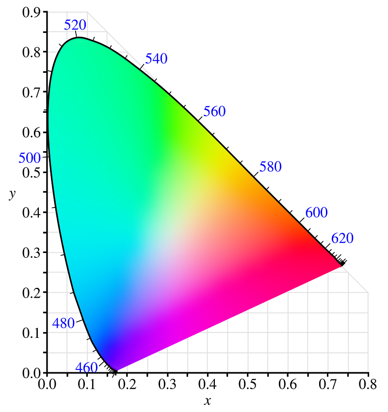
Assuming each color, be it Red, Green, or Blue, is given a value between 0 and 256. Where 0 means the color is not visible at all, and 255 denotes full visibility. In the figure below, you can see how different combinations of these colors at different intensities will generate different colors.
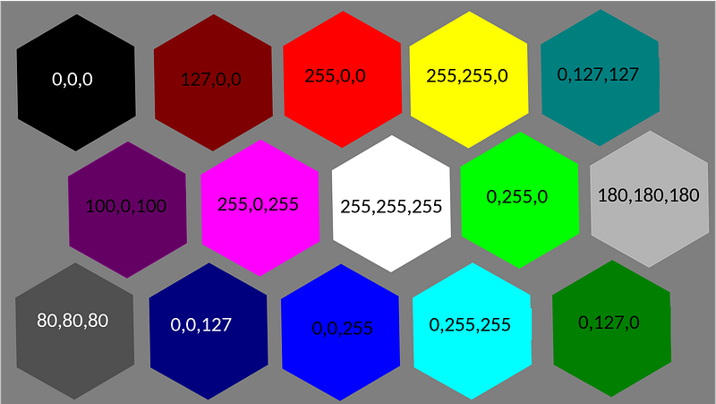
Finally, any number, letter, or color can be represented by a binary number, hence can be generated using transistors.
The takeaway
As humans, microelectronics made of transistors are everywhere around us, in our smartphones, laptops, desktops, smart gadgets, cars, ATMs, and even Drones, following the same logic; The binary language is everywhere as well. Hence, it might be really nice to have a glimpse behind the scenes of the binary magic.
This article was the second article in a series of three articles:
⚫ Transistors: The Greatest Invention of the 20th Century.
⚫ Transistors: The Binary Magic.
⚫ Transistors: Let’s Time-Travel Together.


