
Robotics: Prototyping Vehicle Control Applications using CAT Vehicle Simulator
How to test your vehicle control in a simulation

The talk of autonomous vehicles has gained a media frenzy in recent years and billions of dollars have been poured into making this technology realizable both by industries as well as academia and government agencies across the world. In an autonomous vehicle, the key component of navigation is autonomous vehicle control. Such autonomous vehicle control might use sensors and feedback for making control decisions. While it remains elusive for a beginner to create such control applications, in this article, I will explain how to use the CAT Vehicle ROS package to create and test such vehicle control.
Before you move forward, make sure to go through my previous article in this series to install ROS and CAT Vehicle package:
- https://rahulbhadani.medium.com/robotics-install-ros-noetic-on-ubuntu-20-04-for-autonomous-driving-applications-d0a3e9eae4f3
- https://rahulbhadani.medium.com/robotics-cat-vehicle-simulator-for-developing-control-applications-e6b19d7b3751
CAT Vehicle APIs for vehicle control applications
While this article is not a tutorial on how to use ROS, it is necessary to understand a few basic things about ROS that can help create some simple control applications. I will try to explain the basics using what is provided through the CAT Vehicle package.
The Launch File
ROS provides a methodology to execute a specialized program called ROS nodes through launch files. ROS nodes do some meaningful tasks (such as executing a control law) and publish messages on a named topic or subscribe to some other messages through a named topic. At the same time, some other ROS nodes can subscribe to messages being published through topics. Topics are like slots and nodes put messages on those slots — some other node can read those slots to get messages.
Launch files have an extension .launch and they are generally in the launch directory of a ROS package. In the case of the CAT Vehicle package, consider the launch file catvehicle_empty.launch . It can be used to create a simulation by typing the following in your terminal:
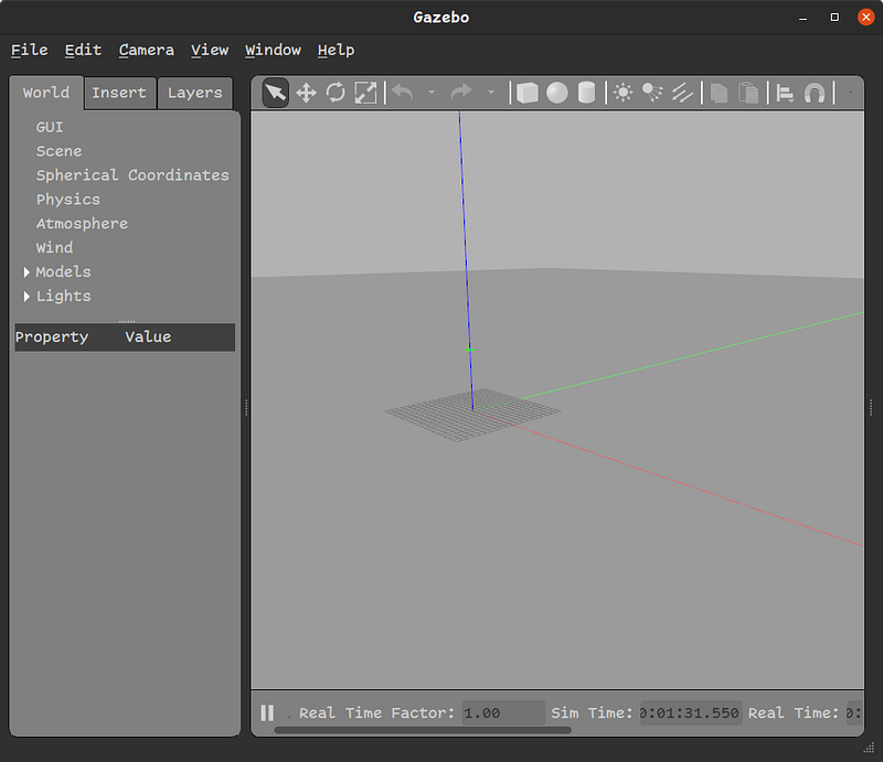
roslaunch catvehicle catvehicle_empty.launchTo see the visual, type the following in another terminal:
gzclientIt launches a window in the Gazebo program showing a virtual world with a ground plane and the center coordinates as shown in Figure 1.
Spawning a vehicle
Spawning a vehicle in the virtual world is done using catvehicle_spawn.launch file in another terminal
roslaunch catvehicle catvehicle_spawn.launchBy default, it creates a vehicle at the origin with the name catvehicle . The launch file provides several command line arguments that can be revealed by pressing the tab a couple of times after typing roslaunch catvehicle catvehicle_spawn.launch in the terminal. We have the following command line arguments:
- camera_left: to enable the left camera mounted on the car.
- camera_right: to enable the right camera mounted on the car.
- laser_sensor: to enable front 2-D Lidar sensor.
- obstaclestopper: to enable a custom control node that prevents collision.
- pitch: specify the pitch in radian.
- robot: the name of the car. You must specify a unique name when spawning multiple cars in the simulation.
- roll: specify the roll in radian.
- triclops: enable front-mounted camera on the car.
- updateRate: specify the update rate of speed of the car published.
- velodyne_points: enable 3D Velodyne Lidar sensor.
- X: specify the X coordinate of the car.
- Y: specify the Y coordinate of the car.
- yaw: specify the yaw of the car in radian.
- Z: specify the Z coordinate of the car.
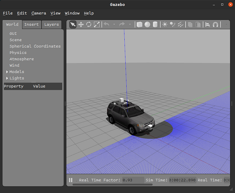
With some of the most essential options, we can spawn a car with the following command-line arguments:
roslaunch catvehicle spawn.launch robot:=ego X:=0.0 laser_sensor:=trueThe above command spawns a car at the center with the name ego and front 2D Lidar sensor enabled. Figure 2 displays the outcome.
Important ROStopics
To develop a control application, we will need to know about some important ROS topics. A full list of topics can be obtained by typing rostopic list and anything that starts with /ego are topics associated with the above car we spawned. /ego/vel is where we get the current driving speed of the car on its linear.x component. Note that each topic has a message type that is equivalent to a C++ structure. You can see the message types of each topic in the output of rostopic list . Interested readers can learn more about ROS messages at http://wiki.ros.org/msg.
The relative speed of any car being followed by a car directly in its front can be found on linear.z component of /ego/rel_vel. It will be zero if there is no car in the front.
Headway distance of the leader car in the front of the car is obtained on the topic /ego/lead_dist .
A control command to the car can be sent on the topic /ego/cmd_vel where you can specify speed on linear.x component and steering angle on angular.z component.
Controller Modeling
For controller modeling, we take the approach of model-based design using Simulink software which is a part of Mathworks’ MATLAB. Simulink provides a library of blocks for specific purposes. One such blocks are ROS toolbox that can be used for creating controller models. Unfortunately, Simulink is not free software. However, you should be able to use it if your institution has purchased a license for it.
Modeling in Simulink
Open MATLAB, in the MATLAB command prompt, type simulink . Select “Create Model” in the Blank Model option. In the empty model workspace, you can see Library Browser where you can choose, drag-and-drop blocks to perform certain tasks. We are interested in blocks from ROS Toolbox or ROS 2 Toolbox. Note that my example is built in MATLAB 2022b. If you want to reproduce my example in an older version of MATLAB, please write to me.
I am interested in a very stupid velocity control shown in Equation 1 which I arbitrarily came up with. This control law is merely for following a vehicle in its front if there is one.
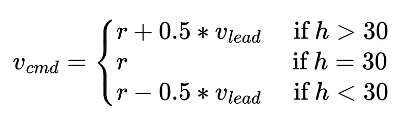
In Equation 1, r is the desired velocity for the ego vehicle (The ego vehicle is the one we are interested in controlling). v_{lead} is the speed of the vehicle or an object directly in the range of the ego vehicle’s front LiDAR sensor. v_{lead} is reconstructed from LiDAR data by differentiating headway h (that is available on /ego/lead_dist topic) and adding to the ego’s current velocity v (obtained from the topic /ego/vel). Differentiated relative velocity is published on /ego/rel_veltopic. v_{cmd} is published on the topic /ego/cmd_vel. Note that /ego/cmd_vel and /ego/vel are different because a vehicle has dynamics so it won’t exactly be driving with what it is commanded to do so. This is how the real world works. We have a hidden transfer function to represent the vehicle dynamics but we don’t model it separately. It is done by rigid body dynamics implemented in the CAT Vehicle package.
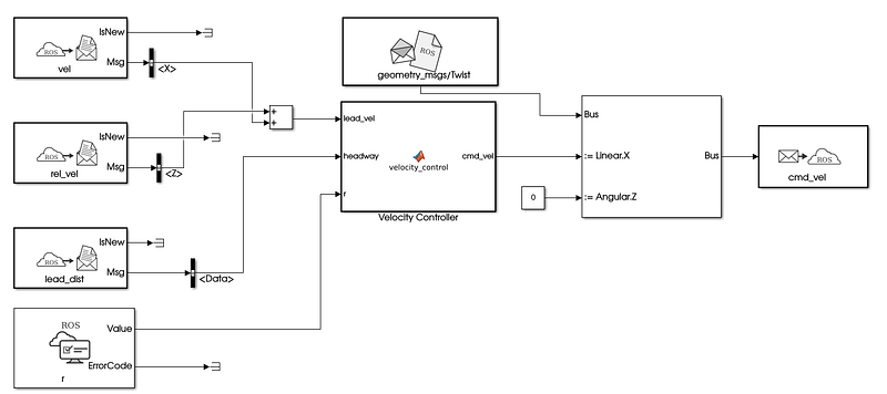
A full model of Equation 1 in Simulink is shown in Figure 3.
Settings for the model
In the Simulink Simulation tab, set the stop time of the simulation to be inf . Now, we specify ROS-related parameters in the Modeling tab -> Model Settings to generate a ROS node. In Model Settings, we will use the following settings:
- Solver -> Type: Fixed Step, Fixed-Step Size: 0.05 (which is in seconds)
- Hardware implementation-> Hardware Board: Robot Operating System, Target Hardware Resources-> Build Options: Build and Load, Catkin Workspace:
~/catvehicle_ws/(or/home/<username>/catvehicle_ws/)
Then press OK. We save the model as velocity_control.slx . You can download the Simulink file used in this example from https://github.com/rahulbhadani/medium.com/blob/master/10-30-2022/velocity_control.slx.
Generating ROS node from the Simulink model
To generate the ROS node, type, roscore in a terminal window, and then in the Simulink ROS tab, press Build & Load. It will compile the model and generate a C++ standalone ROS node in ~/catvehicle_ws/src.
Creating a launch file for the ROS node
The first step in running the simulation is to create a launch file. Create a new text file in your favorite editor and copy the following code:
<?xml version="1.0" encoding="UTF-8"?>
<launch>
<arg name="robot" default="ego"/>
<arg name="r" default="20.0"/>
<param name="/$(arg robot)/r" type="double" value="$(arg r)"/>
<group ns="ego">
<node pkg="velocity_control" type="velocity_control" name="velocity_control_node" output="screen"/>
</group>
</launch>Save the text file as velocity_control.launch in the launch folder of catvehicle package (which may be in ~/catvehicle_ws/src/catvehicle/launch directory).
Simulation Setup
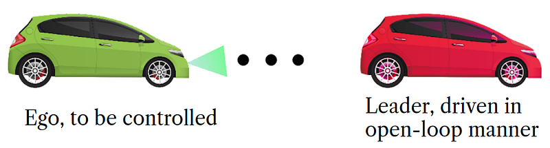
We will consider a two-vehicle simulation where the first vehicle or the leader vehicle will drive with an open loop trajectory specified from a data file. You can download the data file from here. The leader vehicle control is executed using velinjector.launch. For the purpose of this tutorial, I am saving data in the home directory. A whole setup is illustrated in Figure 4.
Running the Simulation
To run the simulation with our velocity controller developed in the Simulink, we will need to execute several roslaunch files in different terminal windows. To make things easier, I have provided a bash script below which will execute all roslaunch at once. Copy them and save them in a run_controller.sh file.
#!/bin/bash
gnome-terminal -- roslaunch catvehicle catvehicle_empty.launch
sleep 5gnome-terminal -- roslaunch catvehicle catvehicle_spawn.launch robot:=leader X:=30.0
sleep 5gnome-terminal -- gzclient
sleep 5gnome-terminal -- roslaunch catvehicle spawn.launch robot:=ego X:=0.0 laser_sensor:=true
sleep 5gnome-terminal -- roslaunch catvehicle velinjector.launch csvfile:=/home/ubuntu/test_data.csv input_type:=CSV time_col:=Time vel_col:=speed robot:=leader str_angle:=0.0
sleep 5gnome-terminal -- roslaunch catvehicle velocity_control.launch robot:=ego r:=2.5
sleep 5gnome-terminal -- rosparam set /execute trueTo run the simulation,
chmod +x run_controller.sh
./run_controller.sh
The above command will open a series of terminal windows and execute all commands one by one.
To log the data in a.bag format, type rosbag record -a . The .bag file can be analyzed using thebagpy package. You can check how to use thebagpy package at https://jmscslgroup.github.io/bagpy.
To terminate the simulation, press Ctrl-C in every terminal window that was popped. To stop the rosbag recording, also press Ctrl-C.
I hope this article was helpful in understanding how to use the CAT Vehicle ROS package and its simulator to develop a simple vehicle control application in the simulation. One can develop much more sophisticated velocity control by leveraging multiple sensor data and possibilities are endless.
Was this helpful? Buy me a Coffee.
Love my writing? Join my email list.
Want to know more about STEM-related topics? Join Medium