

Residential Broadband TV and IP Multicast — Nokia 7750 and Juniper MX on GNS3
Introduction
For anyone who had attended any broadband networking conferences in 2000s, triple-play and MPLS were the buzzwords at that time similar to today’s NFV and SDN. Triple-play means carrying video, voice and data traffic on a common network platform such as MPLS to take advantage of its QoS capability to satisfy the bandwidth, latency and jitter requirements of the traffic.
Today, most of the residential broadband services (e.g., phone, TV, on-demand movie and Internet) sold by carriers employ triple-play networking technology for cost effective service delivery. If we drill down into this triple-play residential broadband services offered by carriers, there are actually 4 types of traffic or services such as:
- Phone (unicast IP voice demanding low traffic latency and jitter)
- Internet (unicast IP best effort data traffic)
- On-demand video such as movies channels (unicast IP video traffic)
- Broadcast TV (Multicast IP video traffic)
Broadcast TV means the same TV channel or IP multicast traffic is shared by many subscribers simultaneously similar to the good old days when TV signal was broadcasted over the air and received by many subscribers using TV antennas.
This article discusses the design and testing of IP multicast in the context of residential broadcast TV deployment. Similar to my other articles in this blog, this residential broadband broadcast TV network is emulated on a PC using GNS3 and we will test various Any Source Multicast (ASM) and Source Specific Multicast (SSM) setups using the emulated multicast network with Nokia SR and Juniper MX routers.
Introduction to Residential Broadband Network
The following shows a typical residential broadband network design using Gigabit Passive Optical Network (GPON) for connecting subscribers to a carriers’ gateways for video, voice and data traffic:
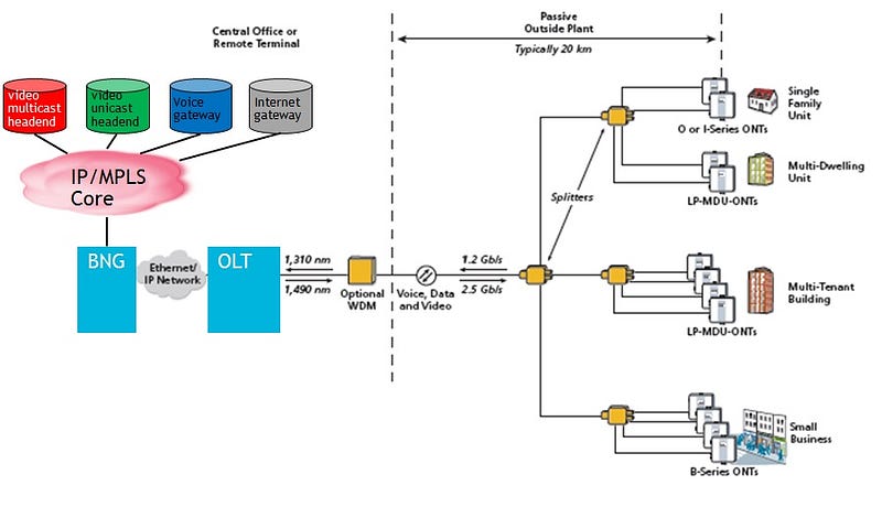
Each subscriber’ traffic is connected to the Optical Network Terminal (ONT) and many kinds of ONTs existed for different deployments such as single family unit and multi-tenant building etc… Optical Line Terminal (OLT) is the first traffic aggregator to aggregate multiple ONTs in a neighborhood to the second traffic aggregator called Broadband Network Gateway (BNG) that further aggregate OLTs in other suburbs to the voice, Internet and video gateways. A typical BNG such as Nokia 7750 and Juniper MX routers can support hundreds of thousands of subscribers.
Residential Broadband Network for Broadcast TV
The aggregation of IP unicast traffic for phone, Internet and on-demand video/movie traffic is relatively straight forward. VLAN-per-subscriber or VLAN-per-service aggregation scheme is normally used to aggregate subscribers’ uni-cast IP traffic to an OLT and then to a BNG. QoS is setup on each component along the path to honor each traffic’s bandwidth, latency and jitter requirements.
Residential broadcast TV network is implemented using either IP PIM or MPLS NG-MVPN standard. The following summarizes the different between the two standards:
PIM (RFC 7761)
- IP based
- Use global routing instance and thus one router can support only one multicast domain
- Use PIM protocol to build the Multicast Distribution Tree (MDT) for multicast traffic delivery via PIM Join and Prune messages
- IP core routers involve in PIM operations such as multicast traffic replication
NG-MPVN (RFC 6513)
- MPLS based to replace the Draft-Rosen VPN IP multicast RFC
- Use VPRN and thus one router can support multiple multicast domains
- PEs run PIM among each other to build the MDT and replicate multicast traffic, if necessary but core P routers are PIM-free for scalability
- PEs form point-to-multiple-point (P2MP) LSPs signaled by RSVP-TE or mLDP across the MPLS core network to transport the MDT’s multicast traffic
Both standards support the deployments of SSM and ASM operations. We will talk about SSM and ASM in more details later.
This article talks about IP multicast network implemented using PIM. We will cover NG-MVPN in the next article. The following shows a typical residential broadband multicast network implemented using PIM to support broadcast TV traffic delivery:
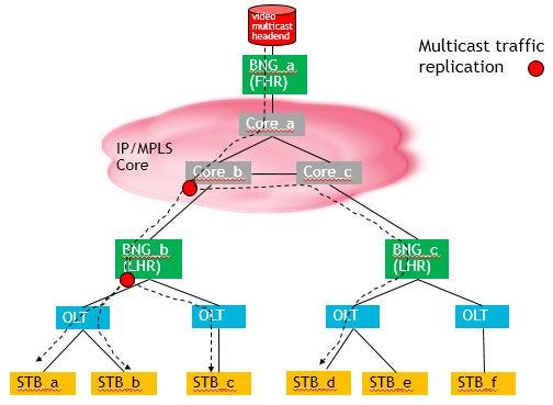
There are 3 BNGs in the above multicast network example. BNG_a is the First Hop Router (FHR) as far as multicast traffic is concerned as it is connected to the video headend. BNG_b and BNG_c are the Last Hop Routers (LHR) as they are connected to the Set Top Boxes (STB) via the OLTs.
If STB_a, STB_b, STB_c and STB_d subscribe to the same broadcast TV channel (e.g., CNN) and the TV channel is mapped to the multicast IP address say, 224.5.6.7, a single IP multicast traffic stream with destination IP address of 224.5.6.7 is sent by the video source through the IP core routers to BNG_b where BNG_b will replicate the multicast traffic to its two downstream OLTs to STB_a, STB_b and STB_c respectively. Since PIM multicast network is used in the above example, the core IP routers may involve in multicast traffic replication, if necessary. In the above diagram, Core_b router replicates the IP multicast traffic for the destination multicast IP address 224.5.6.7, and deliver the multicast traffic or broadcastTV channel via BNG_c to STB_d. As we can see, the video source just delivers one stream of traffic for a given multicast IP address or broadcast TV channel and a MDT is built by the PIM routers for that multicast IP address and the “branches” of the MDT depend on the subscription of the STBs.
The creation of a MDT for a given multicast destination address or a broadcast TV channel via PIM protocol is the first key ingredient for efficient broadcast TV delivery in a residential broadband network over WAN. The second key ingredient is the IETF’s RFC 1112 standard for mapping a multicast IP address to an Ethernet multicast MAC address. Conceptually, an OLT and its associated ONTs form a logical Ethernet switch. When multiple STBs within an OLT subscribe to the same broadcast TV channel represented by say, IP multicast address 224.5.6.7, the STBs will use their regular source MAC address to send the IGMP Join message but at the same time, the STBs listen to the IP multicast mapped MAC address. In this particular case, IP multicast address of 224.5.6.7 is mapped to Ethernet multicast MAC address of 01:00:5e:05:06:07 according to the RFC 1112. In other words, when the LHR deliveries the multicast video stream for the IP multicast address 239.1.2.3, the destination MAC address used will be 01:00:5e:05:06:07 and thus all STBs subscribed to this broadcast TV channel represented by IP multicast address 224.5.6.7 receive the traffic simultaneously without any further traffic replication among the OLT, ONT, and STB.
GNS Multicast Lab Setup
OK, enough for the IP multicast background information for the operations of a residential broadcast TV network. Let us setup a PIM broadcast TV network on a PC using GNS3 using Nokia SR and Juniper MX routers as follows:
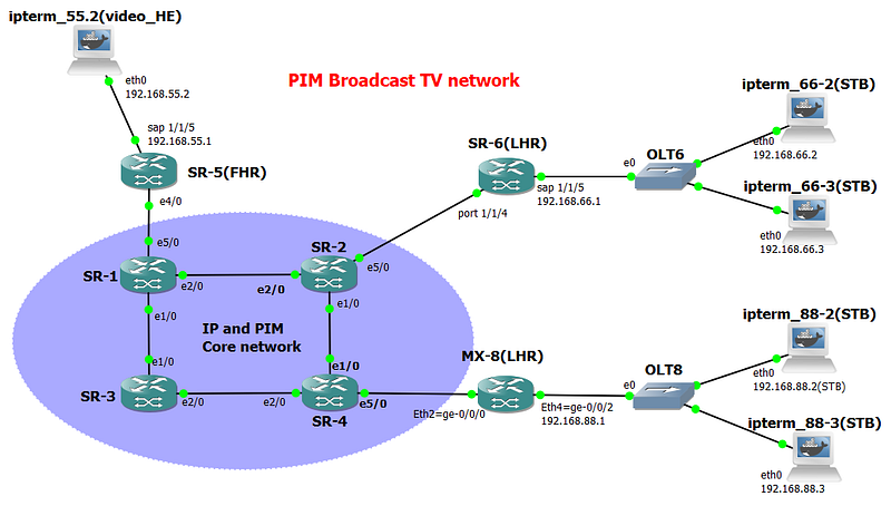
The objective of the lab is to verify the IP multicast traffic distribution from the video source, ipterm_55.2 to all the STBs connected to OLT6 and OLT8. All OLTs are implemented in GNS3 by Ethernet switches. When multiple STBs subscribe to the same broadcast TV channel or IP multicast address, a single video stream from ipterm_55.2 with the specified destination IP multicast address is sent and then replicated by the PIM routers, if necessary to the STBs.
Docker container, gns-ipterm is used instead of the built-in GNS3′ VPCS as the ipterm Docker container supports mtool for sending and receiving multicast traffic. For more information about adding Docker containers on GNS3, please refer to https://docs.gns3.com/14EmmKdryY3FiMOQEclSyHQ3MUlycDGE_DwNPC8L4GIc/index.htm.
GNS3 has a set of official Docker containers such as gns3/ip-term that can be pulled from https://hub.docker.com/u/gns3/?page=1 but other Docker containers such as Firefox or WordPress can also be used, if desired. You can browse the ten of thousands of ready-to-use Docker containers at http://hub.docker.com for incorporation into your GNS3 test setup.
The steps to provision PIM SSM and ASM multicast network are:
- Enable IGP such as ISIS among all PIM routers — There is no need to advertise OLT and STB subnets in ISIS as multicast traffic follow the MDT instead of IGP
- All LHRs have IGMP interfaces to their OLTs
- All routers have PIM adjacency among each other to build the MDT. Make sure the FHRs have a PIM interface to the video headend to listen to the multicast source traffic
- Setup ASM config such as RP, if desired
- Setup SSM config such as Source/Multicast groups mapping, if desired
Step 1 — PIM Routers’ IGP
This blog uses ISIS as IGP. ISIS setup on Nokia 7750 and Juniper MX routers have been covered many times in this log and thus only the routing table with ISIS routes are shown for illustration only.
A:SR-6# show router route-table

====================================================================
Route Table (Router: Base)
====================================================================
Dest Prefix[Flags]                 Type    Proto     Age        Pref
      Next Hop[Interface Name]                        Metric
--------------------------------------------------------------------
10.1.2.0/27                        Remote  ISIS      10h21m07s  18
       10.2.6.2                                          126
10.1.3.0/27                        Remote  ISIS      10h21m07s  18
       10.2.6.2                                         189
10.1.5.0/27                        Remote  ISIS      10h21m07s  18
       10.2.6.2                                         189
10.2.4.0/27                        Remote  ISIS      10h21m07s  18
       10.2.6.2                                         126
10.2.6.0/27                        Local   Local     10h32m51s  0
       toR2                                             0
10.3.4.0/27                        Remote  ISIS      10h20m40s  18
       10.2.6.2                                         189
10.3.7.0/27                        Remote  ISIS      10h20m43s  18
       10.2.6.2                                         199
10.4.8.0/27                        Remote  ISIS      10h20m40s  18
       10.2.6.2                                         189
10.10.100.1/32                     Remote  ISIS      10h21m08s  18
       10.2.6.2                                         126
10.10.100.2/32                     Remote  ISIS      10h21m08s  18
       10.2.6.2                                         63
10.10.100.3/32                     Remote  ISIS      10h20m44s  18
       10.2.6.2                                         189
10.10.100.4/32                     Remote  ISIS      10h20m41s  18
       10.2.6.2                                         126
10.10.100.5/32                     Remote  ISIS      10h21m08s  18
       10.2.6.2                                         189
10.10.100.6/32                     Local   Local     10h33m20s  0
       system                                           0
10.10.100.8/32                     Remote  ISIS      09h17m42s  18
       10.2.6.2                                         189
192.168.55.0/24                    Remote  ISIS      10h21m08s  18
       10.2.6.2                                         252
192.168.66.0/24                    Local   Local     10h32m51s  0
       toOLT6                                           0
192.168.88.0/24                    Remote  ISIS      09h17m42s  18
       10.2.6.2                                         289
--------------------------------------------------------------------
No. of Routes: 18
Step 2 — IGMP between LHR and STB
To understand the broadcast TV channel (i.e., multicast IP address) that a STB wants to subscribe via IGMP Join (S, G), a LHR needs to have an IGMP interface to the OLTs to the STBs. The following shows the IGMP config for SR-6 (Nokia) and MX-8 (Juniper):
SR-6’s IGMP config
A:SR-6>admin# /configure service ies 700
A:SR-6>config>service>ies# info
----------------------------------------------
            interface "toOLT6" create
                address 192.168.66.1/24
                sap 1/1/5 create
                exit
            exit
            no shutdown

A:SR-6# configure router igmp
A:SR-6>config>router>igmp# info
----------------------------------------------
            interface "toOLT6"
                query-interval 15
                no shutdown
            exit
            no shutdown
MX-8’s IGMP config
root@MX-8> show configuration
interfaces {
    ge-0/0/0 {
        description "to IP Core Network via SR-4";
        unit 0 {
            family inet {
                address 10.4.8.8/27;
            }
            family iso;
            family mpls;
        }
    }
    ge-0/0/2 {
        description "to OLT8";
        unit 0 {
            family inet {
                address 192.168.88.1/24;
            }
        }
    }
}
protocols {
    igmp {
        interface ge-0/0/2.0 {
            version 3;
        }
        interface ge-0/0/0.0 {
            disable;
        }
    }
By default, Nokia 7750 and Juniper MX routers use IGMP version 3 and 2 respectively. Since IGMP version 3 supports Source Specific Multicast (SSM) that is desired for the lab, we set MX-8’s ge-0/0/2 to support IGMP version 3 as well.
Use the following commands to verify the status of the IGMP Interfaces
SR-6’s IGMP interface status
A:SR-6# show router igmp interface

====================================================================
IGMP Interfaces
====================================================================
Interface          Adm  Oper Querier         Cfg/Opr Num     Policy
                                             Version Groups
--------------------------------------------------------------------
toOLT6             Up   Up   192.168.66.1    3/3     0       none
--------------------------------------------------------------------
Interfaces : 1
MX-8’s IGMP interface status
root@MX-8> show igmp interface
Interface: ge-0/0/2.0
    Querier: 192.168.88.1
    State:         Up Timeout:    None Version:  3 Groups:      0
    Immediate leave: Off
    Promiscuous mode: Off
    Passive: Off
There is no IGMP group registered yet at the LHRs, SR-6 and MX-8 yet as the STBs have not yet started subscribing any broadcast TV channels or IP multicast addresses.
Step 3 — PIM Interface and Multicast Distribution Tree
The primary objective of PIM is to built the most efficient MDT for a given multicast IP address or a broadcast TV channels for the subscribed STBs. Since we are running PIM instead of NG MVPN, all routers have PIM adjacencies with each other. The following shows the PIM interfaces for the FHR and LHRs:
SR-5’s PIM config
A:SR-5>config>router>pim# info
----------------------------------------------
            interface "toR1"
            exit
            interface "toPC55.2_Video_HE"
            exit
            rp
                bsr-candidate
                    shutdown
                exit
                rp-candidate
                    shutdown
                exit
            exit
            no shutdown
SR-6’s PIM config
A:SR-6# configure router pim
A:SR-6>config>router>pim# info
----------------------------------------------
            interface "toR2"
            exit
            rp
                bsr-candidate
                    shutdown
                exit
                rp-candidate
                    shutdown
                exit
            exit
            no shutdown
MX-8’s PIM config
root@MX-8> show configuration
protocols {
    pim {
        interface ge-0/0/0.0 {
            mode sparse;
        }
        interface lo0.0 {
            mode sparse;
        }
    }
Step 4 — ASM Setup and Verification
The nature of ASM is that the STBs do not know the IP address of the video Source for a particular broadcast TV channel or IP multicast address. For example, the STBs may be programmed with TV channel “CBC Toronto” represented by the IP multicast address 224.1.2.3. However, in ASM, the STBs do not know the IP address of the video source that is responsible for streaming “CBC Toronto” or IP multicast address 224.1.2.3.
Both the video sources and the LHRs use Rendezvous Points (RPs) as a match maker to let STBs to discover the IP address of a video source for a given multicast IP address or broadcast TV channel. The following shows the ASM config for LHRs SR-6 and MX-8. Note that SR-3 (10.10.100.3) is the RP responsible for all IP multicast channels 224.0.0.0/8:
SR-6 PIM ASM config
A:SR-6# configure router pim
A:SR-6>config>router>pim# info
----------------------------------------------
            interface "toR2"
            exit
            rp
                static
                    address 10.10.100.3
                        group-prefix 224.0.0.0/8
                    exit
                exit
                bsr-candidate
                    shutdown
                exit
                rp-candidate
                    shutdown
                exit
            exit
            no shutdown
MX-8 PIM ASM config
root@MX-8> show configuration
protocol {
    pim {
        rp {
            static {
                address 10.10.100.3 {
                    group-ranges {
                        224.0.0.0/8;
                    }
                }
            }
        }
        interface ge-0/0/0.0 {
            mode sparse;
        }
        interface lo0.0 {
            mode sparse;
        }
    }
SR-3’s system interface address 10.10.100.3 is used as the RP’s address for simplicity
SR-3 PIM RP config
A:SR-3>config>router>pim>rp# back
A:SR-3>config>router>pim# info
----------------------------------------------
            interface "system"
            exit
            interface "toR1"
            exit
            interface "toR4"
            exit
            rp
                static
                    address 10.10.100.3
                        group-prefix 224.0.0.0/8
                    exit
                exit
                bsr-candidate
                    shutdown
                exit
                rp-candidate
                    shutdown
                exit
            exit
            no shutdown
SR-5 PIM ASM config
A:SR-5>config>router>pim# info
----------------------------------------------
            interface "toR1"
            exit
            interface "toPC55.2_Video_HE"
            exit
            rp
                static
                    address 10.10.100.3
                        group-prefix 224.0.0.0/8
                    exit
                exit
                bsr-candidate
                    shutdown
                exit
                rp-candidate
                    shutdown
                exit
            exit
            no shutdown
To test the ASM setup, use msend on PC55 to stream ASM traffic to the IP multicast address 224.5.6.7, which represents a broadcast TV channel say, CBC Toronto.
root@ipterm_55:~# msend -g 224.5.6.7 -i 192.168.55.2 -t 10
Now sending to multicast group: 224.5.6.7
Sending msg 1, TTL 10, to 224.5.6.7:4444:
Sending msg 2, TTL 10, to 224.5.6.7:4444:
On all STBs, run mreceive to receive the multicast traffic
root@ipterm_66-2(STB):~# mreceive -g 224.5.6.7 -i 192.168.66.2
Now receiving from multicast group: 224.5.6.7
Receive msg 1 from 192.168.55.2:4444:
Receive msg 2 from 192.168.55.2:4444:
root@ipterm_88-2(STB):~# mreceive -g 224.5.6.7 -i 192.168.88.2
Now receiving from multicast group: 224.5.6.7
Receive msg 1 from 192.168.55.2:4444:
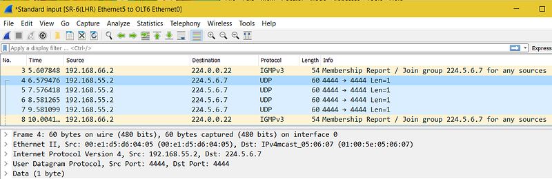
Receive msg 2 from 192.168.55.2:4444:One of the benefits of using network emulators such as GNS3 or EVE-NG on a PC to verify network setup is the ease of use of the built-in Wireshark for packets capture and analysis. On GNS3, if we invoke Wireshark on the link between LHR SR-6 and OLT6 and run mreceive 224.5.6.7 on PC66–2 to receive the multicast stream from the video source PC-55, the destination Ethernet multicast MAC address of 01:00:5e:05:06:07 is used by PC-55 to address all STBs in OLT6 that are interested in the broadcast TV channel represented by the IP multicast address 224.5.6.7.
All STBs should now receive the multicast traffic 224.5.6.7 from PC55 even though PC55 sends out only one single stream of traffic. The PIM routers along the MDT replicate the traffic, whenever necessary to the STBs.
A:SR-6>config>router>pim# show router pim group

====================================================================
Legend:  A = Active   S = Standby
====================================================================
PIM Groups ipv4
====================================================================
Group Address    Type                Spt Bit  Inc Intf       No.Oifs
   Source Address   RP                  State    Inc Intf(S)
--------------------------------------------------------------------
224.5.6.7        (*,G)                        toR2           1
   *                           10.10.100.3
224.5.6.7        (S,G)               spt      toR2           1
   192.168.55.2                10.10.100.3
--------------------------------------------------------------------
Groups : 2
Examining SR-2’s PIM group shows that it is replicating the multicast traffic for multicast address 224.5.6.7 as it has two outgoing interfaces to SR-6 and SR-4 (for MX-8):
A:SR-2# show router pim group

====================================================================
Legend:  A = Active   S = Standby
====================================================================
PIM Groups ipv4
====================================================================
Group Address    Type                Spt Bit  Inc Intf       No.Oifs
   Source Address    RP                  State    Inc Intf(S)
--------------------------------------------------------------------
224.5.6.7        (*,G)                        toR1           1
   *                           10.10.100.3
224.5.6.7        (S,G)               spt      toR1           2
   192.168.55.2                10.10.100.3
--------------------------------------------------------------------
Groups : 2
Step 5 — SSM Setup
For SSM, the STBs or the LHRs know the source IP address of the video sources for a given SSM multicast address. The following shows the additional SSM config to make the PIM routers ready to support SSM:
SR-6’s LHR SSM config
A:SR-6>config>router>igmp# info
----------------------------------------------
            ssm-translate
                grp-range 232.1.1.1 232.255.255.255
                    source 192.168.55.2
                exit
            exit
            interface "toOLT6"
                query-interval 15
                no shutdown
            exit
            no shutdown
MX-8’s LHR’s SSM config
root@MX-8> show configuration
protocols {
    igmp {
        interface ge-0/0/2.0 {
            version 3;
            ssm-map ssm-232_asm-224;
        }
        interface ge-0/0/0.0 {
            disable;
        }
    }
}
routing-options {
    multicast {
        ssm-groups [ 232.0.0.0/8 ];
        asm-override-ssm;
        ssm-map ssm-232_asm-224 {
            policy ssm_asm_policy01;
            source 192.168.55.2;
        }
    }
}
protocols {
    igmp {
        interface ge-0/0/2.0 {
            version 3;
            ssm-map ssm-232_asm-224;
        }
        interface ge-0/0/0.0 {
            disable;
        }
    }
policy-options {
    policy-statement ssm_asm_policy01 {
        term 10 {
            from {
                route-filter 232.0.0.0/8 longer;
            }
            then accept;
        }
        term 20 {
            from {
                route-filter 224.0.0.0/8 longer;
            }
            then accept;
        }
        then reject;
    }
To test SSM, run msend to send traffic to the SSM multicast address range of 232.0.0.0/8. All STBs subscribing to the SSM multicast IP address of 232.1.2.3 receive the IP multicast traffic.
root@ipterm_55:~# msend -g 232.1.2.3 -i 192.168.55.2 -t 10
Now sending to multicast group: 232.1.2.3
Sending msg 1, TTL 10, to 232.1.2.3:4444:
Sending msg 2, TTL 10, to 232.1.2.3:4444:
root@ipterm_66-2(STB):~# mreceive -g 232.1.2.3 -i 192.168.66.2
Now receiving from multicast group: 232.1.2.3
Receive msg 1 from 192.168.55.2:4444:
Receive msg 2 from 192.168.55.2:4444:
root@ipterm_88-2(STB):~# mreceive -g 232.1.2.3 -i 192.168.88.2
Now receiving from multicast group: 232.1.2.3
Receive msg 1 from 192.168.55.2:4444:
Receive msg 2 from 192.168.55.2:4444:
Verify the PIM groups at the LHRs.
SR-6’s PIM group for SSM
A:SR-6# show router pim group

====================================================================
Legend:  A = Active   S = Standby
====================================================================
PIM Groups ipv4
====================================================================
Group Address    Type                Spt Bit  Inc Intf       No.Oifs
   Source Address   RP                  State    Inc Intf(S)
--------------------------------------------------------------------
232.1.2.3        (S,G)                        toR2           1
   192.168.55.2
--------------------------------------------------------------------
Groups : 1
MX-8 SSM PIM group for SSM
root@MX-8> show pim join
Instance: PIM.master Family: INET
R = Rendezvous Point Tree, S = Sparse, W = Wildcard

Group: 232.1.2.3
    Source: 192.168.55.2
    Flags: sparse,spt
    Upstream interface: ge-0/0/0.0

Instance: PIM.master Family: INET6
R = Rendezvous Point Tree, S = Sparse, W = Wildcard
Conclusion
We just show the ASM and SSM configs on Nokia SR and Juniper MX routers to support residential broadcast TV setup. The two key ingredients for efficient IP multicast (i.e., broadcast TV channels) traffic replication are:
- Multicast traffic replication by the PIM routers according to the setup of the MDT based on the TV channel subscription of the STBs
- RFC 1112 to map a multicast IP address to an Ethernet multicast MAC address for efficient Ethernet multicast traffic delivery by OLT/ONT to the STBs
You can follow me on www.medium.com for all my current and future articles on 5G Core, IP/MPLS and software technology.

Originally published at http://clcnetwork.wordpress.com on September 2, 2017.


