
Reefwing AHRS Arduino Library for Drones — Part 1
The Reefwing AHRS library provides an Attitude and Heading Reference System (AHRS) class for use with Arduino compatible boards. The library has been tested with the Arduino Nano, Nano 33 BLE, Nano 33 BLE SENSE (REV 1 and REV 2), Nano 33 IoT, MKR Vidor 4000, Portenta H7 and the Seeed XIAO nRF52840 Sense boards.
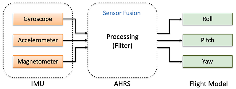
An Attitude and Heading Reference System (AHRS) takes information from the Inertial Measurement Unit (IMU) and processes it to provide reliable roll, pitch and yaw angles (Figure 1). Our library can be downloaded using the Arduino IDE Library Manager, or directly from the Reefwing GitHub Repository.
The initial version of this library was released in February 2022. It is now time for a substantial update!
We wrote about the sensor changes in the Nano 33 BLE revision 2 boards in an earlier article. Version 2 of the Nano 33 BLE Sense, replaces the LSM9DS1 9 axis IMU with a combination of two IMUs, the BMI270, a 6 axis gyro & accelerometer and the BMM150, a 3 axis magnetometer. In order to support the new hardware, it makes sense to separate the sensor processing from the sensor fusion algorithms.
Consequently, we are pulling out the LSM9DS1 IMU code from the Reefwing AHRS Library and have released it as a separate Library. The LSM9DS1 library is targeting the Nano 33 BLE and Nano 33 BLE Sense Rev 1 Arduino boards.
Similarly, we removed the LPS22HB barometer code from our AHRS library and released a stand alone Library for the LPS22HB Pressure Sensor, found in the Arduino Nano 33 BLE Sense Revisions 1 and 2.
Reefwing IMU Types
Reefwing IMU Types is a common library header which is used to prevent duplicate definition of similar types, classes and enums. It also ensures that changes will flow through to all of the Reefwing libraries that use it.
The libraries that use this definition header are:
The Structs Defined in the IMU Types Library are:
EulerAnglesInertialMessageRawDataScaledDataTempDataSensorDataVectorData
The Class Defined in the IMU Types Library is:
Quaternion
We have also included definitions of the I²C addresses for the following devices:
LSM9DS1AG_ADDRESS— Address of the LSM9DS1 accelerometer & gyroscopeLSM9DS1M_ADDRESS— Address of the LSM9DS1 magnetometerHTS221_ADDRESS— Nano 33 BLE Sense Rev 1 Sensor — temp/humidityHS3003_ADDRESS— Nano 33 BLE Sense Rev 2 Sensor — temp/humidityLSM6DS3_ADDRESS— Seeed Studios xiao Sense gyro/accelerometerMPU6000_ADDRESS— TDK InvenSense MPU6x00 gyro/accelerometerMPU6050_ADDRESS— TDK InvenSense MPU6050 gyro/accelerometer
Library Dependencies
To use the Reefwing AHRS Library, you need to also install the Reefwing_imuTypes library. Both of these are able to be installed from the Arduino IDE Library Manager.
Euler Angles
A gyroscope reports angular rates with respect to the sensor. So if our sensor is mounted to a drone which is pitching, rolling and yawing then the measured rates will be in the frame of the rotating sensor (i.e., the aircraft reference frame) NOT a fixed world reference frame. In order to combine angles from different sensors they all need to be in the same reference frame. For this purpose it makes sense to use a fixed frame.
Euler angles are three angles used to describe orientation with respect to a fixed coordinate system. The idea is that we can define any point in 3D space by performing three rotations around the axis of our fixed coordinate system. The order of the rotation matters, so we need to be consistent with this.
The fixed coordinate system used for Euler angles is called the “inertial” or “world” coordinate system. This coordinate system is chosen as a global reference frame that remains fixed in space. In the Euler angle representation known as the “roll-pitch-yaw” convention, the rotations are applied successively about the fixed axes of the inertial coordinate system. The sequence typically follows the order of rotations:
- Roll: Rotation about the fixed x-axis of the inertial coordinate system.
- Pitch: Rotation about the fixed y-axis of the inertial coordinate system.
- Yaw: Rotation about the fixed z-axis of the inertial coordinate system.
You can read more about how we translate our sensor readings to a fixed reference frame in Part 5 of our series on How to Write your own Flight Controller Software.
One of the problems with Euler angles, is that for certain specific values the transformation exhibits discontinuities, a phenomenon called Gimbal Lock (see below).
Inertial Coordinate System and NED
The inertial coordinate system is closely related to the NED (North-East-Down) coordinate system, which is a commonly used local-level coordinate system in navigation and aerospace applications.
The inertial coordinate system, also known as the Earth-Centered Earth-Fixed (ECEF) coordinate system, is a global reference frame with its origin located at the center of the Earth. It is fixed with respect to the Earth and does not rotate with respect to the Earth’s rotation. The x-axis typically points towards the intersection of the equator and prime meridian (0 degrees latitude, 0 degrees longitude). The y-axis points eastward along the equator, and the z-axis points along the Earth’s rotational axis, typically aligned with the North Pole.
The NED coordinate system, on the other hand, is a local-level coordinate system that is commonly used for navigation purposes. It is defined with respect to a specific location or observer on the Earth’s surface. The origin of the NED coordinate system is typically set at the observer’s position, and the NED axes are aligned such that:
- The North axis (N) points towards true North.
- The East axis (E) points towards true East.
- The Down axis (D) points vertically downward, perpendicular to the Earth’s surface.
The NED coordinate system is relative to the observer’s position and orientation, while the inertial coordinate system is fixed with respect to the Earth. However, the relationship between the two coordinate systems can be established through appropriate coordinate transformations.
To convert between NED and inertial coordinates, one typically needs to consider the observer’s position and the rotation of the Earth. This transformation involves accounting for the observer’s latitude, longitude, and altitude, as well as considering the Earth’s rotation rate. For these reasons, we will stick with the inertial reference frame.
Sensor Fusion
Sensor fusion is the process of combining sensory data or data derived from disparate sources such that the resulting information has less uncertainty than would be possible when these sources were used individually. With the gyroscope and accelerometer, we have two angle sensors which should be providing the same data but with different errors. The concept is to combine or fuse the data in such a way as to eliminate the errors and produce an accurate angle that we can use.
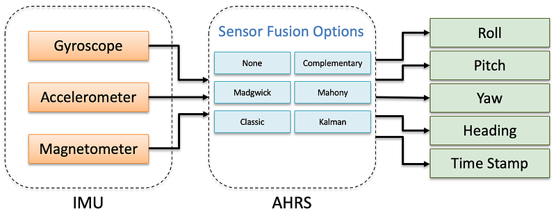
In the original release of our AHRS Library, all the sensor fusion algorithms were contained within the IMU class. In version 2.2, these have been moved to the new ReefwingAHRS class (Figure 2). Now data from any IMU can be used as inputs to our sensor fusion algorithms. The Reefwing AHRS provides the following Sensor Fusion options:
- Classic Complementary Filter
- Quaternion Complementary Filter
- Madgwick Filter
- Mahony Explicit Complementary Filter (ECF)
- Kalman Filter (6 DOF)
- No sensor fusion
A free parameter is defined as a variable in our sensor fusion algorithm which cannot be determined by the model and must be estimated experimentally or theoretically. A detailed explanation of the free parameters and the sensor fusion algorithms is provided in Part 7 of our series on writing your own flight control software.
Gimbal Lock
Gimbal lock is a physical and mathematical phenomenon. For physical gimbals, it results in the loss of one degree of freedom and occurs when two gimbal axes are parallel.
Both the Apollo 11 and Apollo 13 missions had gimbal lock incidents.
On these spacecraft a set of physical gimbals were used for the IMU.
The NASA engineers knew about the issue and their “solution” was having
the flight computer flash a gimbal lock warning at 70° and then freeze
the IMU at 85°, at which point the IMU was no longer available.

In this situation, the spacecraft would have to be moved away from the
gimbal lock position, and then the IMU manually realigned using the
stars as a reference.
In our context, gimbal lock is a problem that arises from the use of Euler Angles to represent the rotation matrix. For Tait-Bryan (ZYX rotation order) angles, you get gimbal lock when the pitch is ±𝜋/2 radians (i.e., ±90°). At this pitch the orientation of the sensor cannot be uniquely represented using Euler Angles.
An AHRS that uses Euler Angles will always fail to produce reliable angle estimates when the pitch approaches 90 degrees. This is an intrinsic issue for Euler Angles and can only be solved by switching to a different representation method — cue quaternions.
Quaternions
Unlike Euler Angles, quaternions are difficult to visualise. There are a lot of detailed explanations regarding quaternions already available, so we will keep our explanation as high level as possible.
Mathematically quaternions are described as a hyper complex number of rank 4, made up of four scalar variables (q0, q1, q2, and q3) and three complex numbers (i, j, and k). The four scalar variables are sometimes known as Euler Parameters, don’t confuse these with Euler Angles.
Quaternions have 4 dimensions, one real dimension (q0) and 3 imaginary dimensions (q1, q2, and q3). Each of these imaginary dimensions has a unit value of the square root of -1, all perpendicular to each other (i, j and k).
You need to be aware that there are two conventions for quaternions,
Hamilton and JPL. The difference between the two conventions is the
relation between the three imaginary bases. In the Hamilton convention,
ijk = −1, while JPL defines ijk = 1. As consequences, the multiplication
of quaternions and the transformation between quaternions and other
rotation parameterizations differ with the quaternion convention used.
As we are using quaternions to only represent rotations, we normalise them to a unit magnitude. The quaternion in terms of axis-angle, 𝜽 is:
q = cos(𝜽/2) + i( x * sin(𝜽/2)) + j(y * sin(𝜽/2)) + k(z * sin(𝜽/2))
  = [cos(𝜽/2)  -x * sin(𝜽/2)  -y * sin(𝜽/2)  -z * sin(𝜽/2)]
where:
- 𝜽 = angle of rotation.
- x, y, z = the vector representing axis of rotation.
We will use the Hamilton quaternion notation (this seems to be the consensus convention, apart from the folks at JPL of course). The quaternion units from q1 to q3 are called the vector part of the quaternion, while q0 is the scalar part. Quaternions are often represented as:
q = q0 + q1i + q2j + q3k = [q0 q1 q2 q3]^T = [qw qx qy qz]^TWe like quaternions because rotations with unit quaternions are less computationally intensive than Euler Angles and they don’t suffer from Gimbal Lock.
For these reasons, we mostly use quaternions to provide the sensor fusion updates in the Reefwing AHRS library. While our Quaternion class is defined in the Reefwing IMU Types library, we have placed the quaternion sensor fusion update methods in the AHRS class, as it made sense to keep them with the other updates. We also didn’t want to over complicate the IMU Types Library.
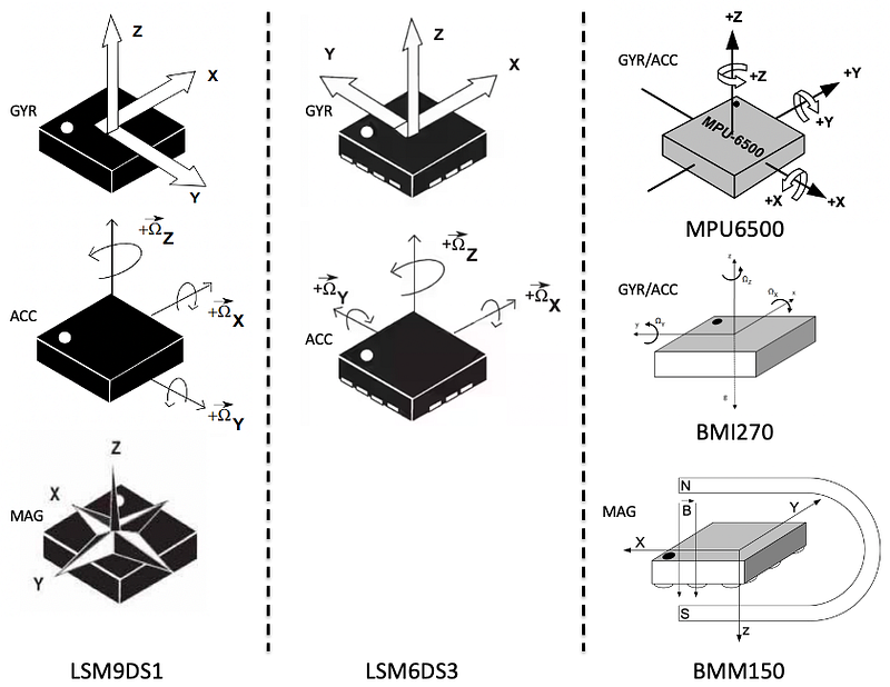
IMU Orientation
IMU sensors don’t have a standardised axis layout (Figure 3). Even if they did, it is the way that they are mounted on your device that is important. This matters most when we are combining data from different sensors like in the LSM9DS1 or the BMI270 and BMM150 on the Nano 33 BLE Rev 2.
In this situation we want to ensure that all the sensors are using the same reference frame. To this end, we have provided the setData(SensorData d, bool axisAlign) method. If axisAlign = true (the default), then when setting the sensor data, the following modifications are done based on IMU type:
LSM9DS1— magnetometer x-axis value is reversed.BMI270_BMM150— magnetometer y-axis value is reversed.
Depending on the sensor combination you are using and their mounting orientation, you may need to do something similar in your sketch. If axisAlign = false, then no modification is made to the loaded sensor data.
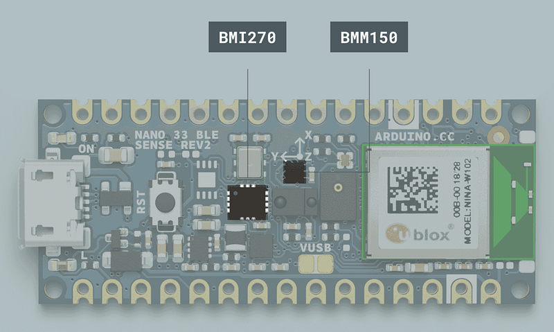
Even though the Nano 33 BLE Sense Rev 2 mounts the two sensors to line up the x-axis (Figure 4), the magnetometer y-axis is still reversed according to the data sheet (Figure 3).
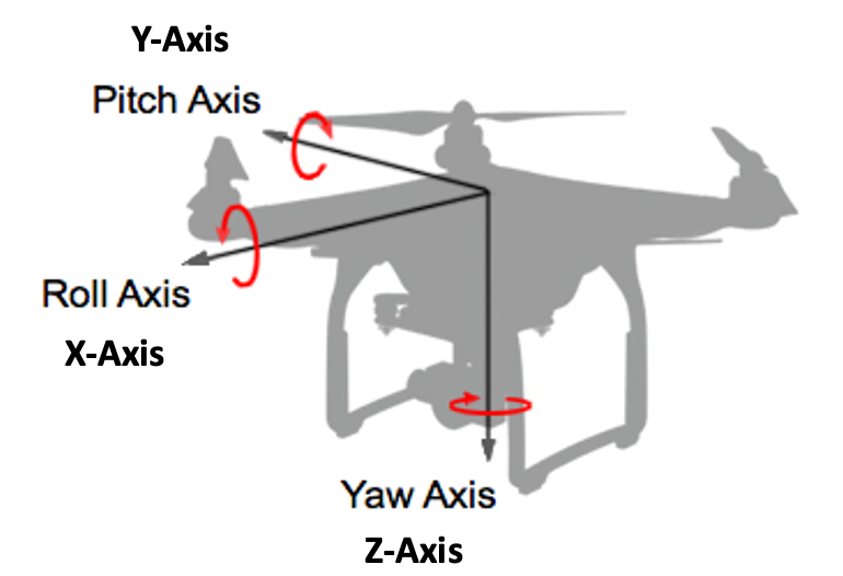
The convention that we use, consistent with the inertial frame euler angles, is that roll is associated with the x-axis, pitch is associated with the y-axis and yaw is associated with the z-axis (Figure 5).
Part 2
In Part 2 of this article we will explain how to use the library and provide hardware specific examples for the Arduino Nano, Nano 33 BLE, Nano 33 BLE SENSE (REV 1 and REV 2), Nano 33 IoT, MKR Vidor 4000, Portenta H7 and the Seeed XIAO nRF52840 Sense boards. These will use the following IMUs:
- LSM9DS1
- LSM6DS3
- BMI270 & BMM150
- MPU6000/MPU6500/MPU6050
If you enjoyed this article and would like to help support my writing, then please show your appreciation by following me, clapping, highlighting or commenting! Alternatively, you can buy me a coffee or subscribe, to get an email whenever I publish a new article.


