avatarShan Jaffry

Free AI web copilot to create summaries, insights and extended knowledge, download it at here

1618

Abstract

gure above that there is an RRC layer both in the gNB and the device. RRC is responsible for handling RAN-related C-plane procedures like:</p><ol><li>Broadcasting <b>System Information (SI): </b>It is necessary for the device to be able to communicate with the cell.</li><li>Transmission of paging messages to notify the device about incoming connection requests.</li><li>Connection management.</li><li>Handling of device capabilities: When a device establishes a connection, the network request device’s capabilities (e.g. if it supports Dual connectivity or massive MIMO etc.)</li><li>Measurement configuration and reporting</li><li>Others…</li></ol><h2 id="d772">How are RRC messages Transmitted?</h2><p id="80d1">RRC messages are transmitted to the device using <a href="https://www.5gfundamental.com/2021/03/5g-nr-difference-bw-default-and.html#:~:text=Default%20bearer%20is%20the%20bearer,subscriber%20when%20first%20time%20attached.&amp;text=Each%20default%20bearer%20comes%20with%20an%20IP%20address%20assigned%20by%20the%20SMF.&amp;text=UE%20can%20have%20additional%20default,for%20different%20types%20of%20services.&amp;text=Each%20default%20bearer%20will%20have%20a%20separate%20IP%20address.">Signalling Radio Bearers (SRBs)</a>. (SRB is a C-plane tunnel created between gNB and UE for control signalling, i.e. RRC or NAS messages are sent over SRBs.)</p><p id="f640">As shown in the figure above, the messages follow the following protocol stack: PDCP, RLC, MAC, and PHY (same as U-plane, except for the SDAP).</p><p id="c5e2">During the connection establishment phase, the SRBs are mapped to the <a href="

Options

https://syedshan85.medium.com/different-channels-in-5g-nr-part-2-4d849c213065"><b>CCCH logical</b> <b>channel</b></a>. Once the connection is established between gNB and the device, SRBs are mapped to <b>DCCH logical channel</b>. In terms of PHY layer mapping, RRC messages are always mapped over<a href="https://syedshan85.medium.com/different-channels-in-5g-nr-part-1-4e030b0c77f7"><b> PDSCH or PUSCH</b></a> (depending on DL or UL transmission).</p><p id="e798">If we notice in Figure 1, C-plane and U-plane data follow the same protocol stack from the PDCP layer which are multiplexed at the MAC layer and transmitted over PDSCH/PUSCH in the same TTI.</p><p id="b3b5">Thus, In the downlink direction, logical to physical channel mapping of RRC message is (UL is similar with the UL channel counterparts) :</p><blockquote id="c6ab"><p><b>CCCH/DCCH</b><b>DL-SCH</b><b>PDSCH</b>.</p></blockquote><h2 id="e9b0">Now, a device is always in some sort of state depending on its activity. These states are the RRC states.</h2><p id="e777">In 5G NR, there are there RRC states</p><ol><li>RRC_IDLE: This is the sleep state where the device is not receiving any data.</li><li>RRC_Connected: This state is used for data transfer between the device and gNB. All parameters necessary for communication are known to both entities. The device is assigned an identity, i.e. C-RNTI, for signalling purposes with the network.</li><li>RRC_Inactive: This is the new state in NR. In this state, the RRC context is kept both at the device and the gNB level. The device-to-core level connection is also kept.</li></ol></article></body>

Radio Resource Control (RRC) in 5G NR

Figure 1. Protocol Stack for U-plane and C-plane messages in 5G NR (Ref. 5G NR by E. Dahlman et al.)

Before discussing RRC directly, let us build some context!

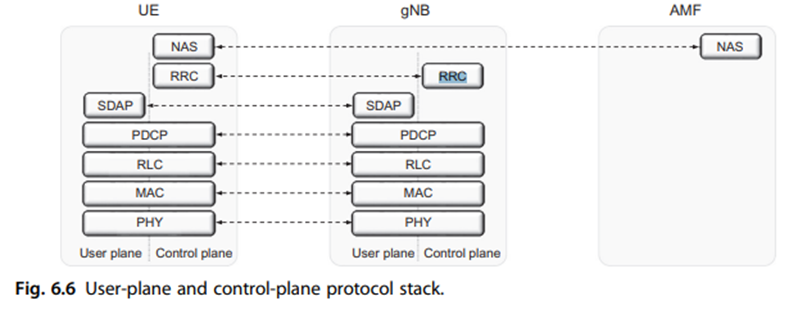
In the 5G NR, Data and Control planes are clearly segregated.

The Data or User plane (U-plane) is responsible for carrying user data via protocol stack as shown in Figure 1 (i.e. SDAP, PDCP, RLC, MAC, PHY).

The Control plane (C-plane) is further divided into two categories:

The first C-plane category is one that runs between the Core Network (5GC) and the user device. It shares control signals via NAS messaging (See the figure above). This device-to-core C-plane functionality is responsible for connection setup, mobility, security etc, and operates between the AMF in the 5GC and the device. (We will discuss NAS messaging in some other blog. But in short, NAS messages are also sent via RRC, but gNB cannot read them. NAS messages are solely between the core and the device)

The second C-plane functionality runs between gNB and the device and is known as RRC (RRC = Radio Resource Control). It terminates at the gNB and has no direct link with the core (but has a transparent link of course… everything is connected to the core as CORE IS THE BIG BOSS!).

Note in the figure above that there is an RRC layer both in the gNB and the device. RRC is responsible for handling RAN-related C-plane procedures like:

  1. Broadcasting System Information (SI): It is necessary for the device to be able to communicate with the cell.
  2. Transmission of paging messages to notify the device about incoming connection requests.
  3. Connection management.
  4. Handling of device capabilities: When a device establishes a connection, the network request device’s capabilities (e.g. if it supports Dual connectivity or massive MIMO etc.)
  5. Measurement configuration and reporting
  6. Others…

How are RRC messages Transmitted?

RRC messages are transmitted to the device using Signalling Radio Bearers (SRBs). (SRB is a C-plane tunnel created between gNB and UE for control signalling, i.e. RRC or NAS messages are sent over SRBs.)

As shown in the figure above, the messages follow the following protocol stack: PDCP, RLC, MAC, and PHY (same as U-plane, except for the SDAP).

During the connection establishment phase, the SRBs are mapped to the CCCH logical channel. Once the connection is established between gNB and the device, SRBs are mapped to DCCH logical channel. In terms of PHY layer mapping, RRC messages are always mapped over PDSCH or PUSCH (depending on DL or UL transmission).

If we notice in Figure 1, C-plane and U-plane data follow the same protocol stack from the PDCP layer which are multiplexed at the MAC layer and transmitted over PDSCH/PUSCH in the same TTI.

Thus, In the downlink direction, logical to physical channel mapping of RRC message is (UL is similar with the UL channel counterparts) :

CCCH/DCCHDL-SCHPDSCH.

Now, a device is always in some sort of state depending on its activity. These states are the RRC states.

In 5G NR, there are there RRC states

  1. RRC_IDLE: This is the sleep state where the device is not receiving any data.
  2. RRC_Connected: This state is used for data transfer between the device and gNB. All parameters necessary for communication are known to both entities. The device is assigned an identity, i.e. C-RNTI, for signalling purposes with the network.
  3. RRC_Inactive: This is the new state in NR. In this state, the RRC context is kept both at the device and the gNB level. The device-to-core level connection is also kept.
5g
Radio Resource Control
Control Plane
5g Protocol Stack
5g Technology
Recommended from ReadMedium