
How to Write your own Flight Controller Software — Part 11
Managing Brushless DC (BLDC) Motors
In part 10 we explained the care and feeding of brushed DC motors. In this article we examine their bushless cousins and how to control them. Controlling brushless DC (BLDC) motors is a lot harder than for brushed, particularly if they don’t include a sensor for rotor position. This is why Electronic Speed Controllers (ESC’s) exist.
1.0 Brushless DC Motors
Brushless DC (BLDC) Motors are like brushed motors but use electronic commutation instead of mechanical. Hence the term brushless. Typically, BLDC motors have a rotating permanent magnet and a fixed armature coil. This makes it easy to connect a voltage across the coil with no need for brushes. BLDC motors are like AC synchronous motors. The major difference is that synchronous motors develop a sinusoidal back EMF, as compared to a rectangular, or trapezoidal, back EMF for brushless DC motors. Both have stator created rotating magnetic fields producing torque in a magnetic rotor. The speed of a brushless DC motor is not fixed unless driven by a phased locked loop slaved to a reference frequency.
CommutationDC Motor Commutation is the process of switching current direction in the armature windings to change the induced magnetic field polarity and produce constant torque in one direction. Commutation can be done mechanically using brushes and a commutator (a rotary electrical switch) or electronically using an Electronic Speed Controller.Unlike brushed DC motors, brushless do not develop maximum torque when stationary. The advantages of BLDC motors over brushed are:
• Better torque to weight ratio. • Better torque per Watt. • Higher range of speeds. • Less acoustic noise, smaller, lighter, and longer life.
The major disadvantage that BLDC motors have compared to brushed motors is that they need an expensive and complicated Electronic Speed Controller (ESC).
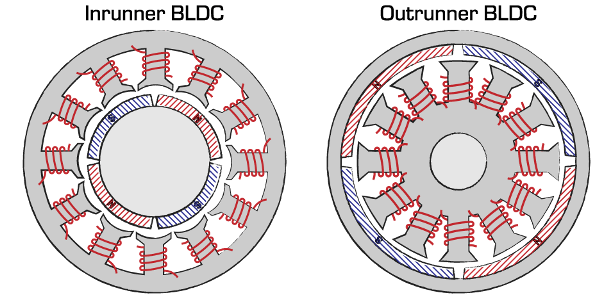
BLDC motors have permanent magnets attached to the rotor and can be divided into two categories (Figure 1):
1. Inrunner — rotor turns inside the stator; and
2. Outrunner — rotor turns outside the stator.
Inrunner motors have lower torque than outrunners but can spin at higher RPM’s. Generally, most drone BLDC motors are outrunners. If the shell of your BLDC motor rotates then the motor is an outrunner.
1.1 Motor Size
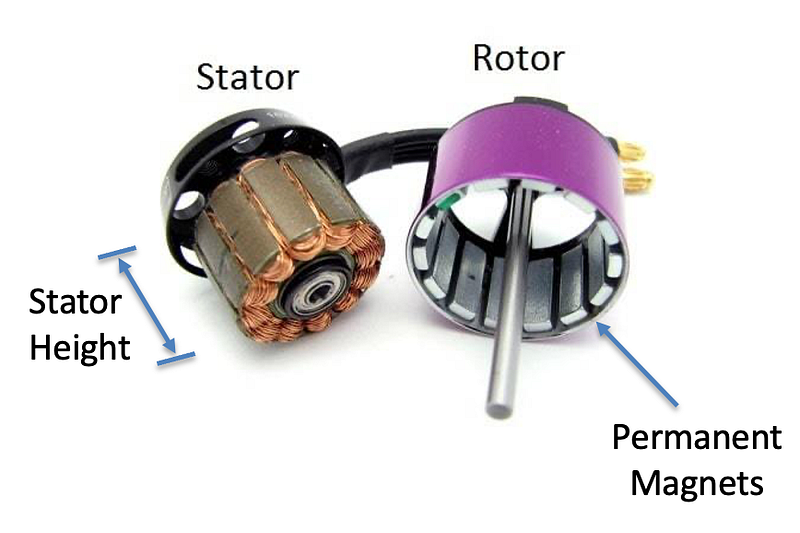
Brushless motor size is normally indicated by a 4-digit number WWHH. WW = stator width in mm’s and HH = stator height in mm’s. For example, the motors used in the 65mm drone class (measured between diagonal motors) are often 0802’s (i.e., with a stator width of 8 mm and height of 2 mm — they are small motors!). Figure 2 illustrates the relevant parts in a disassembled brushless motor.
1.2 Motor Phases
Another way to characterise BLDC motors is by the number of phases (i.e., the number of separate stator windings — see Figure 3). Single-phase, two-phase and three-phase are available with single-phase and three-phase being the most popular.
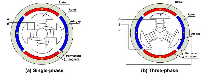
A single-phase motor has one stator winding, wound either clockwise or counter-clockwise along each arm of the stator, to produce four magnetic poles as shown in Figure 3. By comparison, a three-phase motor has three windings. Each phase turns on sequentially to make the rotor revolve.
2.0 Brushless DC Motor Control
In BLDC motors we use electronic switches to achieve commutation and rotate the motor shaft.
2.1 Single-Phase BLDC Motor
For a single-phase BLDC motor, you can use a H-bridge to reverse the current. Electronic commutation requires feedback on the rotor position to generate maximum torque. The easiest way to accurately detect position is to use a position sensor (e.g., hall effect sensor).
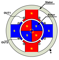
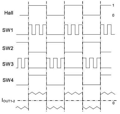
If we mount a position sensor at location (a) in Figure 4 and assume the sensor goes HIGH when the rotor’s North Pole passes and LOW when the South Pole passes, then the association between the Hall Effect position sensor and drive timing is shown in Figure 5. The ripple in the armature current (IOUT1–2) is due to the PWM switching. The applied voltage, switching frequency, and PWM duty cycle are the three key parameters which determine the speed and the torque of the motor.
2.2 Single-Phase BLDC Motor Control without a Position Sensor
To save money you can get motors which don’t have rotor position sensors. Control of these motors uses the Back Electromotive Force (BEMF) which is generated through the interaction of the moving rotor magnets and the stator coils. Detecting motor position via BEMF has the following challenges:
- A minimum motor speed is required to generate sufficient back EMF to be sensed.
- Abrupt changes to the motor load can cause the BEMF drive loop to lose synchronization.
- The BEMF voltage can be measured only when the motor speed is within a limited range of the ideal commutation rate for the applied voltage.
- Proper motor start-up and synchronization is required.
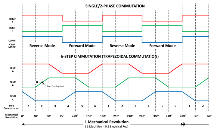
With three phase BLDC motors, 2 coils are energised and the third is left floating. You can monitor the voltage on the third coil and detect when it crosses zero volts. This can be used to determine rotor position and schedule commutation. With a single-phase BLDC motor, the coil is always energised but the current direction is swapped to drive rotation in one direction. The BEMF signal in a single-phase motor will be more like a square wave than the trapezoidal signal found with three phase motors (Figure 6).
Motor commutation on a single or two-phase BLDC motor can be timed using the BEMF changes in state, in other words the rising/falling edge of the BEMF signal is used instead of a zero crossing. The detection of a rising/falling edge can be done by a comparator. Each time a BEMF edge is detected, the motor controller or more specifically, the Complementary Waveform Generator (CWG) reverses current direction in the stator coil (Figure 7).
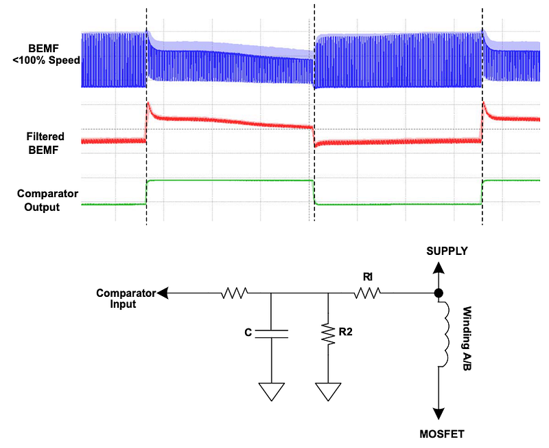
In a real motor, the BEMF signal will not be a clean square wave. PWM speed control and other sources will introduce noise which can make edge detection tricky. BEMF filtering is required to ensure reliable detection and hence successful sensorless commutation (Figure 8).
A common approach to BEMF filtering is to use a RC low pass filter in conjunction with a voltage divider. The components are selected to filter out as much as the high frequency noise as possible with introducing delays in the BEMF signal. We can apply the design criteria provided in the Microchip Application Note AN266255:
- At low frequencies, the circuit behaves as a normal voltage divider. Vout = (R2/(R1+R2) Vin
- At high frequencies, C acts like a short to GND, filtering away the high frequency noise.
- The corner frequency of this first order filter is: 𝛚0 = (R1 + R2) / (R1 × R2 × C).
- To minimise filter current, R1 + R2 ≥ 10 to 100 kΩ .
2.3 BLDC Motor Pre-positioning and Start-up
We mentioned that one of the challenges of sensorless BLDC motor control is that a minimum motor speed is required to generate sufficient back EMF to be sensed. This is because BEMF is directly proportional to motor speed. Consequently, during motor start-up we need to pre-position the rotor and use an open loop control strategy until the motor is rotating quickly enough to provide position information via BEMF (Figure 9).
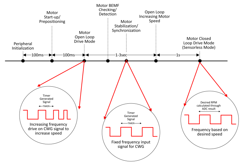
Prepositioning of the rotor is done by gradually increasing the voltage applied to the coil and waiting a given period until the rotor has settled into a known position. The motor is then started in an open loop fashion, with inter-commutation time based on a predetermined table of inter-commutation delays, stored in FLASH/EEPROM. This sequence is executed without attention to the BEMF. During the open loop control phase, motor speed is gradually increased until the target level is reached. As the speed increases the firmware starts to detect and monitor the motor BEMF response. At this point the speed controller code changes to closed loop mode.
If the motor fails to synchronize and rotate after this sequence, stall detection will be triggered, allowing the firmware to re-execute the process with different inter-commutation periods. This procedure continues until the motor successfully starts rotating. When it is rotating, the final inter-commutation time values will become the default values and used the next time that power is applied. This method works well when the motor load is known in advance.
As the applied voltage varies with the frequency at a certain ratio, this start-up procedure is known as variable-voltage variable-frequency control. The ratio of supply voltage and commutation frequency is motor and load dependent.
2.4 Single-Phase Sensorless Commutation
Sensorless commutation can be implemented using a comparator, Complementary Waveform Generator (CWG) and several timer interrupts (Figure 10). The comparator is used to detect the rising/falling edge of the filtered BEMF signal. The comparator Fixed Voltage Reference (FVR) is set so that the BEMF magnitude will trigger and sustain stable motor rotation.
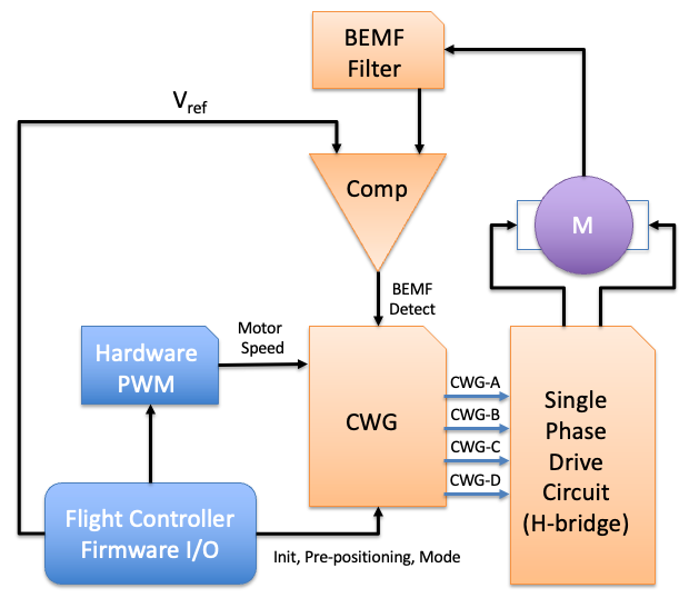
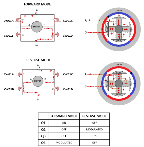
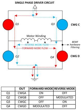
When a change in state of the filtered BEMF signal is detected, the comparator will trigger a timer interrupt that tells the CWG to toggle its mode from Forward to Reverse. For a single-phase BLDC motor, the CWG Forward and Reverse modes can be used to drive the H-Bridge MOSFET’s alternately. MOSFET switches are used to alternately energize the motor windings, allowing current to flow in opposite directions. Figure 11, shows the CWG drive modes for a single-phase BLDC motor.
The CWG (Figure 12) is available as a peripheral in some microcontrollers (e.g., Microchip PIC’s [5]) with no processor overhead. These peripherals include functions like selectable input sources, dead-band control, polarity control, auto-shutdown, and auto-recovery. The CWG generates a two-output complementary waveform from one of several selectable input sources. The off-to-on transition of each output can be delayed from the on-to-off transition of the other output, thereby creating a time delay immediately where neither output is driven. This is referred to as the dead-band. You could also implement a CWG in software if you wanted.
We have seen previously that exceeding a motors maximum torque loading will cause the motor to stall and generate maximum current through the stator windings. This may damage the motor so often a low value shunt resistor will be used to monitor the motor current. The voltage drop across the shunt resistor varies linearly with respect to the motor current. By measuring the voltage across this resistor using an ADC or comparator, we can trigger auto-shutdown in the CWG if an overcurrent situation occurs.
Specifying a Shunt ResistorSeveral parameters are important in specifying a shunt resistor. Shunt resistors have a maximum current rating. The resistance value is given by the voltage drop at the maximum current rating. For example, a shunt resistor rated for 100 A and 50 mV has a resistance of 50 / 100 = 0.5 mΩ. The voltage drop at maximum current is typically rated 50, 75 or 100 mV.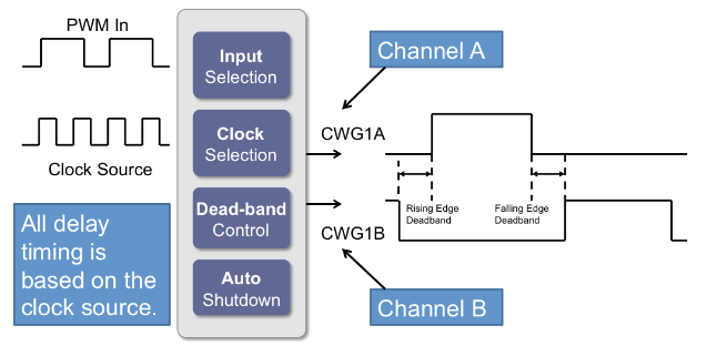
2.5 Three-Phase BLDC Motor
Rotation of a 3-phase BLDC motor is achieved by individually altering the magnitude and direction of current into each of the 3 coils, changing the direction of the magnetic fields generated by the stationary coils (Figure 6). Each set of coils is individually energized in a particular order that creates a series of electromagnetic forces to keep the rotor in motion. This requires 3 power wires to supply current to each set of coils (Figure 13).
There are three control schemes for electronic commutation: trapezoidal, sinusoidal, and field-oriented control (FOC).
The trapezoidal technique is the simplest. At each step, two windings are energized (one “high” and one “low”) while the other winding floats. The downside of the trapezoidal method is that this ‘stepped’ commutation causes the torque to ‘ripple’, especially at low speeds.
Sinusoidal control is more complex, but it reduces torque ripple. During this control regime, all three coils remain energized with the driving current in each of them varying sinusoidally at 120° from each other. The result is a much smoother power delivery compared with the trapezoidal technique.
Field-oriented control (FOC) relies on measuring and adjusting stator currents so that the angle between the rotor and stator flux is always 90°. This technique is more efficient at high speeds than the sinusoidal method and gives better performance during dynamic load changes compared to all other techniques. There is virtually no torque ripple, and smoother, accurate motor control can be achieved at both low and high speeds. FOC can handle rapid acceleration changes without generating instability, allowing the drone to perform complex manoeuvrers while maximizing efficiency.
We will only discuss the trapezoidal control scheme in detail. The other two are beyond the scope of this article (i.e., I don’t understand them well enough to explain them).
2.6 Trapezoidal Control of a 3 Phase BLDC Motor
The trapezoidal motor control algorithm has the following main characteristics:
- Motor control based on a six-phase switching sequence (refer to Figure 6 for an illustration of this).
- Detection of the magnetic angle of the rotor, used to set the correct angle; each step corresponds to a 60°angle.
- In sensorless control systems, the switching angle is estimated by measuring the BEMF phase voltage.
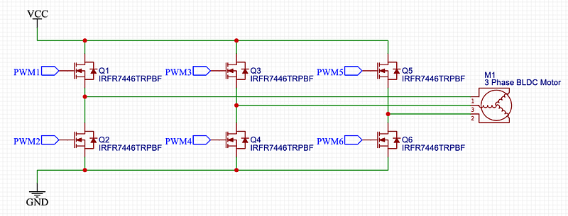
You can use three pairs of power MOSFET’s arranged in a bridge structure to sequentially apply power to the three phases of a BLDC motor (Power Stage — Figure 14). This is a similar arrangement to the H-bridge that we saw earlier and in fact if your current requirements are modest, you could use a couple of L298 chips to control a 3-phase motor. The L298 is the big brother of the L293. The L293 we spoke about in our H-bridge circuit is a quadruple driver that can employ half a H-bridge if you only need the motor to rotate in one direction. The L298 has greater voltage and current capacity (up to 46 V and 2 A per channel) and is a dual full-H bridge. You can’t use half a bridge in the L298. A heat sink is included in L298 due to the larger current capability.
Figure 14 doesn’t show the pull-up and pull-down resistors which are required at the driver inputs to ensure that they are OFF immediately after a microcontroller RESET. After RESET, the microcontroller outputs are configured as high impedance inputs.
One precaution that must be taken with this type of driver circuit is that both high side and low side drivers must never be activated at the same time. This will result in a large shoot through current, likely destroying the FET’s as VCC is shorted to GND.
The power MOSFET’s are controlled using pulse-width modulation (PWM) which converts the input DC voltage into an average driving voltage. The use of PWM allows the start-up current to be limited and offers precise control over speed and torque. The PWM frequency is a trade-off between the switching losses that occur at high frequencies and the ripple currents that occur at low frequencies, and which in extreme cases, can damage the motor. Ideally, designers use a PWM frequency of at least an order of magnitude higher than the maximum motor rotation speed. To compare, the frequency in hertz is equal to the revolutions per minute (RPM) divided by 60.
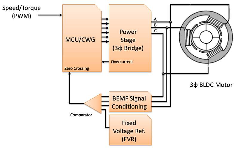
As an example, the BR2205 motors used in the Magpie have a Kv = 2300 and run on a 2S LiPo battery with a nominal voltage of 7.4 V.Unloaded Motor RPM = Kv × V = 2300 × 7.4 = 17,020Unloaded Motor Frequency (Hz) = RPM / 60 ≈ 284 HzWith 3.1-inch propellers fitted the loaded motor RPM @ 75% PWM was measured to be just over 13,800 RPM. Larger props will load the motors more but ideally, we want the PWM frequency to be around 2 kHz.The default Arduino Servo library PWM frequency is 50 Hz.Similar to a brushed DC motor, the current that a motor draws is directly proportional to the torque load on the motor shaft. Motor current is determined from the motor torque constant KT.Torque (𝛕) = KT × IAThe product of KT and KV is the same for all motors:KV × KT = 1Unfortunately, motor control is not as simple as Figure 14. We need the following components (Figure 13):
- A microcontroller (MCU) to provide the 3-phase pulse timings. Usually separate but could be part of the flight controller (e.g., as a separate core or thread).
- The 3-phase motor to be controlled.
- Motor power stage (AKA 3-phase bridge). The motor power stage is a standard triple half-bridge setup as shown in Figure 14.
- BEMF Filter — as discussed for single-phase BLDC motor control.
- PWM for motor speed input. The motor speed/torque is controlled by pulse width modulation (PWM).
- BEMF Signal Conditioning. The three-phase motor voltages are connected to the ADC via a voltage divider and LPF. The low pass filter should be designed to filter out as much high frequency noise as possible without introducing a notable delay to the back-EMF signal. The ADC sample of the floating phase voltage should be timed to occur when the PWM switching noise is low.
- BEMF Zero Crossing Detection Circuit. The conditioned BEMF signal is fed into a comparator to identify when a zero crossing occurs. This is done by comparing it with a Fixed Voltage Reference (FVR). The zero crossing occurs right in the middle of two commutations. At constant speed, or slowly varying speed, the time from one commutation to zero-crossing and the time from zero-crossing to the next commutation are equal.
- Motor Overcurrent Detection Circuit. Again, like single-phase control, we measure the voltage across a shunt resistor to determine motor current. Due to commutation and PWM this current will have a lot of high frequency noise that will need to be low pass filtered. Voltage across the shunt resistor is normally low enough to not require a voltage divider for the ADC input. The frequency of ADC measurements will determine how quickly the motor is switched off in an overcurrent event. If a faster reaction is required, an external comparator could be used to trigger an interrupt.
The three MOSFETs connected to VCC in Figure 14 are referred to as the high side switches and those connected to GND are the low side switches. In trapezoidal control, only one high side and one low side switch is open at any time, creating a closed circuit where the current runs into one phase winding and out of another phase winding, while the last phase winding is left floating.
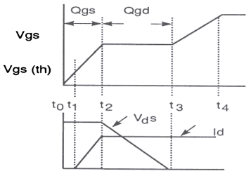
Important MOSFET ParametersMOSFET stands for Metal Oxide Semiconductor Field Effect Transistor. Unlike the Bipolar Junction Transistor (BJT) which is current driven, MOSFET’s are voltage driven. This makes them a bit more intuitive to use. Instead of the base, emitter and collective found on a BJT we have a gate, drain and source (Figure 15).BJT’s are switched on by a biasing current applied to the base of the transistor. This base current turns the BJT on, allowing an amplified flow of current from the collector to the emitter of the transistor. FET’s have such a high input impedance that they draw little current through the gate. If the voltage across the gate and source (VGS) is greater than a threshold voltage (VTH) then the transistor turns on and current can flow from the drain to source.When designing the power stage of your ESC using MOSFET’s there are some important parameters to consider when selecting your device:- Drain Source Voltage (VDS): Maximum voltage across the drain and source terminals in the OFF state before the transistor breaks down.- Drain Current (ID): Maximum current capability from drain to source when the FET is ON. This needs to be higher than the motor maximum current.- Drain Source Resistance (RDS): Resistance between the drain and source when transistor is ON. You want this low to minimise the voltage drop across the FET when it is ON.- Total Power (PTOT): Maximum power dissipation of the FET. May require a heatsink.- Threshold Voltage (VTH): If VGS < VTH then FET is OFF (cut-off state) and if VGS > VTH then FET is ON (saturation state).- Gate Charge (QG): Is the charge required at the gate to turn the FET ON. More importantly, it can be used to work out the effective gate capacitance (CGS) which controls switching speed. Don’t use input capacitance (CISS), this will be significantly smaller than the effective capacitance.Effective CGS = QG / VGSAs shown in Figure 16, the FET doesn’t turn on and off instantly. A quick and dirty estimate of turn on time can be found using the effective capacitance time constant.𝛕 = RG × Effective CGSThe time constant (𝛕) is the time it takes a capacitor to charge up 63.2% or discharge 36.8%. At 5𝛕 a capacitor is considered fully charged, to reach 90% of charge takes 2.3𝛕, 80% charged is 1.4𝛕. Pick the point you consider the FET on and use the equivalent time constant multiplier.Alternatively, you can calculate transition time using the gate charge (QG) and gate current (IG):ttransition = QG / IGIn many applications it is the driver current (IG), which is the limiting factor for switching speed, not the MOSFET.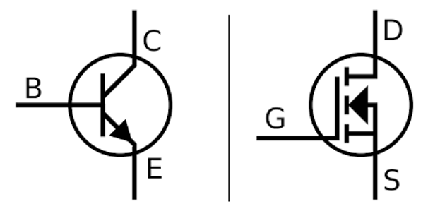
2.7 PWM and MOSFET Switching
Depending on the MOSFET selected, you could drive them directly from Arduino I/O pins. Normally though you will see a gate driver between the MCU and power stage MOSFET’s. To understand why we need this, we need to look at what happens to the gate current during switching.
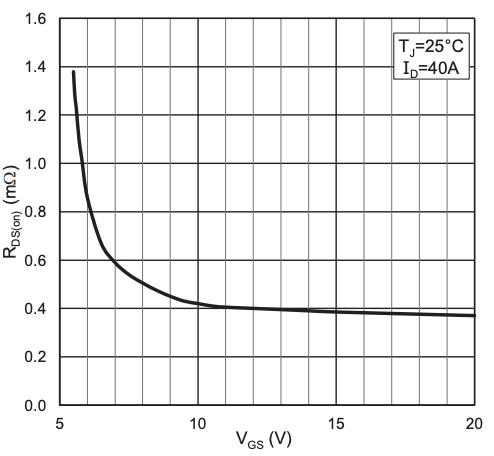
To turn a MOSFET OFF, the gate is held at a voltage close to the source voltage (i.e., VGS ≈ 0). To turn it ON, VGS needs to be raised above the threshold voltage (VTH) until RDS becomes low enough that the voltage drop from drain to source (VDS) is negligible. We don’t want to be wasting power heating up the FET’s. A typical graph of VGS vs RDS for a power MOSFET is shown in Figure 17.
If a MOSFET is switched OFF and ON rapidly, like with PWM, then we will observe the gate current waveform shown in Figure 18. This shows the characteristic charge and discharge curve of a capacitor. While this current peak will only last for a few hundred nanoseconds, its value is significantly higher than the average gate current required (Iav). Therefore, we need a gate driver if we want to modulate the BLDC motor speed using PWM. An Arduino board can’t source or sink sufficient current when turning the MOSFET on and off quickly.
The area under each current spike in Figure 18, is equivalent to the MOSFET gate charge parameter QG. When selecting a MOSFET for your power stage, the smaller the QG the quicker it will switch, all else being equal.
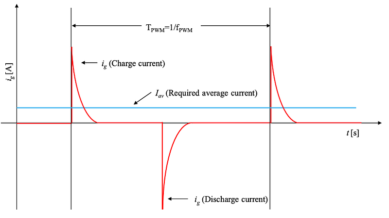
It is possible to calculate the average current that must be provided to continuously switch a MOSFET on and off at a particular frequency. If the PWM frequency is fPWM then the average current (Iav) is:
Iav = fPWM × QG
If you are switching more than one MOSFET (N) per PWM cycle, then the average current becomes:
Iav = fPWM × QG × N
To comply with EMC requirements, it may be necessary to slow the rate of MOSFET switching which will increase FET power dissipation. The usual approach is to add a resistor between the gate driver and gate. This will increase the effective capacitance time constant and, hence charging rate. By doing this, peak switching current (Figure 18) will decrease and switch on/off times will increase.
Common mode noise, differential noise, radiated noise and bearing noise are various types of EMI noise which are generated by high frequency pulse width modulation (PWM) switching.2.8 Open Loop Control
An interesting property of brushless DC motors is that they will operate synchronously to a certain extent. This means that for a given load, applied voltage, and commutation rate the motor will maintain open loop lock with the commutation rate provided that these three variables do not deviate by a significant amount.
This happens because if the commutation rate is too slow for an applied voltage, the BEMF will be too low resulting in more motor current. The motor will react by accelerating to the next phase position then slow down waiting for the next commutation. Since the motor can accelerate faster than the commutation rate, rates much slower than the target can be tolerated without losing lock but at the expense of excessive current.
On the other hand, if commutation is too fast, then commutation occurs early before the BEMF has reached its peak resulting again in more motor current and a greater rate of acceleration to the next phase, but it will arrive there too late. The motor tries to keep up with the commutation but at the expense of excessive current.
If the commutation arrives so early that the motor cannot accelerate fast enough to catch the next commutation, lock is lost and the motor spins down. This happens abruptly not very far from the target rate.
The abrupt loss of lock looks like a discontinuity in the motor response which makes closed loop control difficult. An alternative to closed loop control is to adjust the commutation rate until self-locking open loop control is achieved. If the supply voltage is well regulated, then the motor can be operated open loop over its entire speed range.
In pulse width modulation the effective voltage is linearly proportional to the PWM duty cycle. An open loop controller can be made by linking the PWM duty cycle to a table of motor speed values stored as the time of commutation for each drive phase. We need a table because revolutions per unit time is linear, but we need time per revolution which is not linear. Looking up the time values in a table is much faster than computing them.
2.9 Acceleration and Deceleration Delay
The inertia of the motor and propeller, delays motor response to changes in the drive voltage. We need to compensate for this delay by adding a matching delay to the control loop. The control loop delay requires two time constants, a relatively slow one for acceleration, and a relatively fast one for deceleration.
Without delays in the control loop, the next speed measurement will be taken before the motor has reacted to the previous adjustment. Adjustments would continue to be made ahead of the motor response until eventually, the commutation time is too short for the applied voltage, and the motor goes out of lock.
As the motor can tolerate commutation times that are too long, but not commutation times that are too short, the acceleration time delay can be longer than required without serious detrimental effect.
To prevent loss of lock, the loop deceleration timer delay must be short enough for the control loop to track or precede the changing motor condition. Overcompensation during deceleration will not result in loss of lock but will cause increased levels of torque ripple and motor current until the target commutation time is eventually reached.
3.0 Back EMF (BEMF)
Electromagnetic Induction was discovered in the 1830’s by Michael Faraday. Faraday noticed that moving a permanent magnet in and out of a coil or a single loop of wire induced an Electromotive Force or EMF, in other words a Voltage. This linkage between magnetism and electricity is called Faraday’s Law of Electromagnetic Induction.
The amount of induced EMF in a coil using a magnet is determined by 3 factors:
- The number of turns of wire in the coil — Induced EMF is proportional to the number of turns.
- The speed of the relative motion between the coil and the magnet.
- The strength of the magnetic field.
The armature coils of our motor move through the magnetic field of the stator and this creates an induced EMF in accordance with Faraday’s Law.
Lenz’s Law states that: “the direction of an induced emf is such that it will always opposes the change that is causing it”. In other words, an induced current will always oppose the motion or change which started the induced current.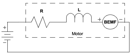
For our motors this means that the induced current will be in the opposite direction to the current from our battery, hence the term back EMF (BEMF — Figure 19). The back EMF is the same as the open-circuit armature voltage.
3.1 Determining BEMF in a 3-Phase Motor
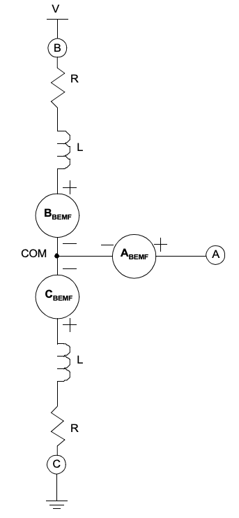
Figure 21 shows the equivalent circuit of a BLDC motor with coils B and C driven while coil A is floating. At the commutation frequency the inductances (L) are negligible. The resistance (R) in each coil is assumed to be the same. The L and R components are not shown in the A phase since no significant current flows in this part of the circuit so those components can be ignored. In sensorless commutation we measure the BEMF voltage in the floating phase to determine rotor position.
The BEMF, relative to the coil common connection point, generated by each of the motor coils, can be expressed as:
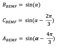
In trapezoidal control there are six drive phases in one electrical revolution. Each drive phase occurs +/- 30 degrees around the peak back EMF of the two motor windings being driven during that phase. Figure 20 is a graphical representation of the BEMF formulas computed over one electrical revolution for terminal A — denoted as BEMF (drive on).
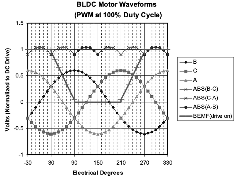
The BEMF (drive on) waveform is linear and passes through a voltage that is exactly half of the applied voltage at precisely 60 degrees which coincides with the zero crossing of the coil A BEMF waveform. This implies that we can determine the rotor electrical position by detecting when the open terminal voltage equals half the applied voltage. Even using PWM to vary motor speed, at the various duty cycles, the BEMF (drive on) curve always equals half the applied voltage at 60 degrees.
4.0 Start-up / Inrush Current
When the rotor of a DC motor is stationary, the only resistance to current flow is the impedance of the electromagnetic coils. The impedance is comprised of the parasitic resistance of the copper in the windings, and the parasitic inductance of the windings themselves. The resistance and inductance are very small by design, so start-up currents would be very large, if not limited.
Start-up current is only limited by the parasitic resistance and inductance of the motor windings, and the current capacity of the power source (i.e., battery). Excessive current can cause driver MOSFETS to blow and circuitry to burn. We can minimize the effects of excessive start-up current by limiting the applied voltage on motor start with pulse width modulation (PWM). Motor speed is directly proportional to applied voltage, so varying the PWM duty cycle linearly from 0% to 100% will result in a linear speed control from 0% to 100% of maximum RPM.
5.0 H-bridge Shoot Through
Shoot through current can lead to catastrophic damage in an H Bridge. It happens when both the High Side and Low Side Power MOSFET’s are ON at the same time.
Even in well-designed systems logic propagation, delays and MOSFET gate capacitances can create a situation where both the High and Low Side devices are both ON. When this condition occurs the current flows directly to ground and bypasses the load.
To prevent this, the drive circuit should be designed with a small delay (deadtime) between turn off and turn on, so that both transistors on the same side (high and low) are never ON simultaneously. The easiest way to implement this deadtime is in software. Drivers take more time to turn off than to turn on, so extra time must be allowed to elapse so that both drivers are not conducting at the same time.
Notice in Figure 6 that the high drive period and low drive period of each output, is separated by a floating drive phase period. This dead time is inherent to the trapezoidal three phase BLDC drive scenario, so special timing for dead time control is not necessary. The trapezoidal BLDC commutation sequence should never switch the high-side device and the low-side device in a phase, at the same time.
If you enjoyed this article and would like to help support my writing, then please subscribe to become a Medium Member. I will get a portion of your subscription fee and you get full access to every story on Medium. Alternatively, you can buy me a coffee!
[1] Image Credit: https://media.monolithicpower.com/document/Brushless_DC_Motor_Fundamentals.pdf
[2] Microchip Application Note AN2662, “Sensorless Drive for Single and Two-Phase Brushless DC Motor Application Note”. Ref: https://www.microchip.com/content/dam/mchp/documents/OTH/ApplicationNotes/ApplicationNotes/AN2662-Sensorless-Drive-forSingle-and-Two-PhaseBLDC-Motor-00002662A.pdf
[3] Microchip Application Note AN1779, “Sensored Single-Phase BLDC Motor Driver”, Ref: https://ww1.microchip.com/downloads/en/Appnotes/00001779A.pdf
[4] Ref: https://www.microchip.com/content/dam/mchp/documents/OTH/ApplicationNotes/ApplicationNotes/AN2662-Sensorless-Drive-forSingle-and-Two-PhaseBLDC-Motor-00002662A.pdf
[5] Ref: http://ww1.microchip.com/downloads/en/AppNotes/90003118A.pdf
[6] Ref: https://microchipdeveloper.com/8bit:cwg
[7] Ref: https://web.archive.org/web/20120324165247/http://www.ti.com/lit/ml/slup097/slup097.pdf
[8] Credit: Allegro Microsystems Application Note 296216, ESTIMATING MAXIMUM MOSFET SWITCHING FREQUENCY, https://www.digikey.jp/Site/Global/Layouts/DownloadPdf.ashx?pdfUrl=7FD0E2425F9F43CDA5A36657E4257030
[9] Ref: http://ww1.microchip.com/downloads/en/AppNotes/00857A.pdf


