
How To Use RTK GPS On A ROS Robot
Get accurate positioning down to 14 mm!
A typical GPS receiver module outputs a position accurate to about 2 meters/6 feet, which is remarkable for such an inexpensive device. However, it’s not good enough to be used as a sole reference point for applications like agriculture, surveying, or mowing. Using RTK GPS, it is possible to get accuracies as good as 14 mm/.55 inch. If you’d like to learn how to integrate a GPS like Sparkfun’s Zed-F9P onto your robot, you’re in the right place!
I recently got my robot navigating between waypoints using RTK GPS, and I’ll share what I learned. Here’s a video clip of it moving between waypoints using RTK GPS for positioning.
How RTK GPS Works
GNSS Realtime Kinematic (RTK) GPS relies on an external correction source from a fixed ground station. It receives signals from the GPS satellite constellation, and because it’s position is accurately known, it can produce correction data usable by other receivers in the region. This station is called the reference or base station. A second receiver, called the roving station, moves around the area being measured. It is the roving station that is mounted to a robot, or carried by a surveyor.
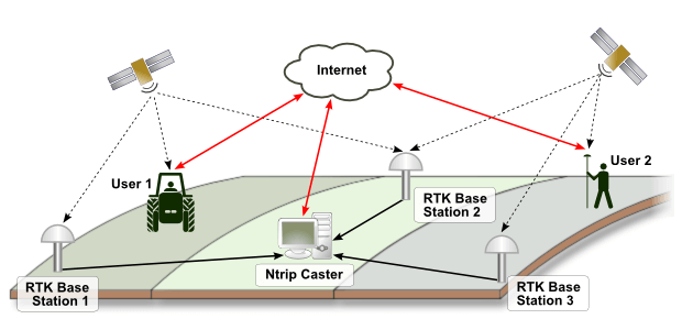
The two must be able to communicate so that the rover can receive correction data from the reference station. In some cases, the reference station also receives position information from the roving station. This communication can be done via internet, cellular connection, or other wireless data transmission. There are a couple of protocols in use for this — the most common, and the one I used, is NTRIP. In the image below, multiple base stations send data to the NTRIP caster server, which provides correction data across a wide area. In this scenario, the rover’s location is used to select the closest base station for the correction data.
Alternatively, you can set up your own base station with a second RTK GPS receiver, and broadcast correction data via WiFi or other radio transmission. In that situation, it would look like this.

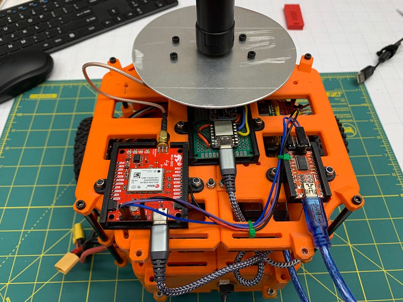
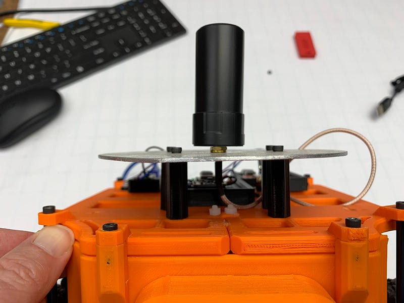
The RTK receiver requires solid signal strength to get the best accuracy. I used an external antenna, and found I got better reception with a properly sized ground plane made from aluminum sheet.
Sources of Correction Data
The reference station can be built and operated by you with a second RTK GPS receiver, or you may be able to find one in your area that is already running to use. I lucked out — the Ohio Department of Transportation runs the CORS Correction Network of reference stations, and allows open access over the internet after a simple registration process. It may take some hunting to find one near you, but if you can, you save the expense of a second RTK GPS to use in your own reference station. You should ideally be within 10 km of a reference station — if you are not, accuracy drops off by about a mm per km farther away that you are.
There are also subscription services available. One example is PointPerfect, offered by uBlox, the manufacturer of the module that the Sparkfun Zed 9FP uses.
This setup is what worked for me, with my correction service — the following should be used as a guide to get you started, but your system will almost certainly require changes to get it to work.
Connecting the GPS
You will want to read the connection information for your correction service carefully, as it may differ from what mine used. The NTRIP caster on the Ohio CORS network requires the rover to send it’s position as part of the client connection. It uses this location to select the nearest base station, and it won’t send correction data without the location.
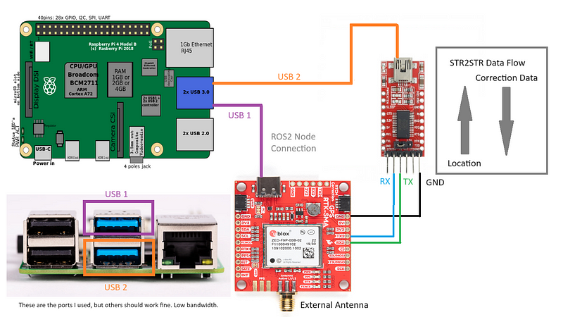
To make this work required two connections to the GPS receiver. The primary UART, a USB-C connection shown in purple in the diagram above, is what the ROS 2 node connects to. The GPS outputs NAVPVT sentences at a rate of 10 hz out of the box.
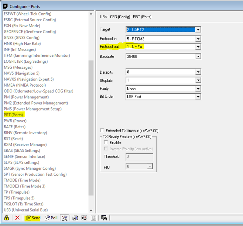
The second UART is used for the NTRIP client. It outputs NMEA sentences with the rover’s position, and takes as input NTRIP correction data.
I had to use the uBlox receiver configuration software to set the second UART to these modes — it was not outputting NMEA sentences out of the box, so the NTRIP caster server was not sending back correction data. There is useful information on that process here.
Software Setup — NTRIP Client
I would first recommend you install the NTRIP client and get it working, independantly of ROS. If your NTRIP caster requires you to send location back to it, as mine did, you’ll need str2str ≥ version 2.4.3 to gain that functionality. You need the -b switch to be included. Compile instructions can be found here: https://github.com/tomojitakasu/RTKLIB/issues/674
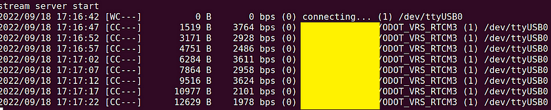
The command I used to start the NTRIP client looked like this. UART2 of the GPS was showing up as ttyACM0 when connected via the USB to serial converter.
If you are getting correction data back, you should see the byte count increasing as shown here, and a non-zero bps transfer rate.
At this point, the GPS is receiving correction information on UART2, and outputting NAVPVT sentences on UART1. We just need to catch them and inject them into ROS. That’s the job of the ROS Ublox node.
Software Setup — ROS Ublox Node
My robot is running ROS 2 Galactic. I have not tested with later versions yet. The ublox_gps package retrieves data from the GPS and publishes the resulting topics. On Galactic, that package is ros-galactic-ublox-gps.
At the time I got it working, I had to make a new YAML configuration file from one of the provided samples. My copy of /opt/ros/galactic/share/ublox_gps/config/zed_f9p.yaml follows. A few settings were tweaked, but I don’t have notes on which ones.
Similarly, I copied an example launch file and modified it to point at the new config file. This is a copy of my /opt/ros/galactic/share/ublox_gps/launch/ublox_gps_node-zed-f9p.py launch file.
I then launch the GPS node like this, after the NTRIP client (str2str) is running.
Understanding the Output
One the node is running, you can see the topics being published as shown.
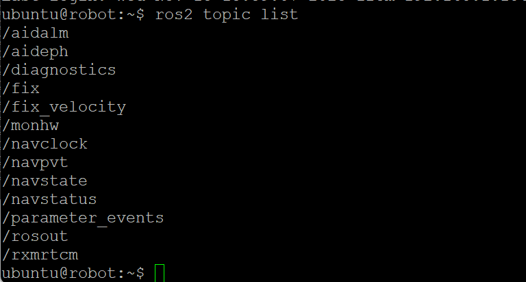
The /navpvt topic contains the precision GPS position, in the fields lat and lon. The field h_acc contains the receiver’s estimate of your horizontal accuracy in millimeters. The fields closely follow the NAVPVT data described in the datasheet. Outdoors, horizontal accuracy starts at 300 mm and drops to 14–25 mm within a few minutes of startup. It is easy to use the h_acc field to wait until your accuracy is at the desired level, and tell when your reception is not ideal. The lat/lon values are scaled up by a large integer value defined in the spec sheet — you need to divide them by that integer to convert back to degrees. The additional accuracy shows up as more decimal places in these measurements.
The IMU and Low Speed Vehicles
The Zed F9P has an onboard IMU, and the node outputs heading based on it. However, I have not figured out how to calibrate it for low speed vehicles like mine. New firmware is available that is supposed to let this be done, but the calibration procedure is not trivial. Without calibration, the heading drifts badly, as one would expect. I found it to not be usable for determining heading on my walking-speed robot. Here is a comparison of GPS heading output vs the IMU’s yaw in a 2.5 meter straight drive.
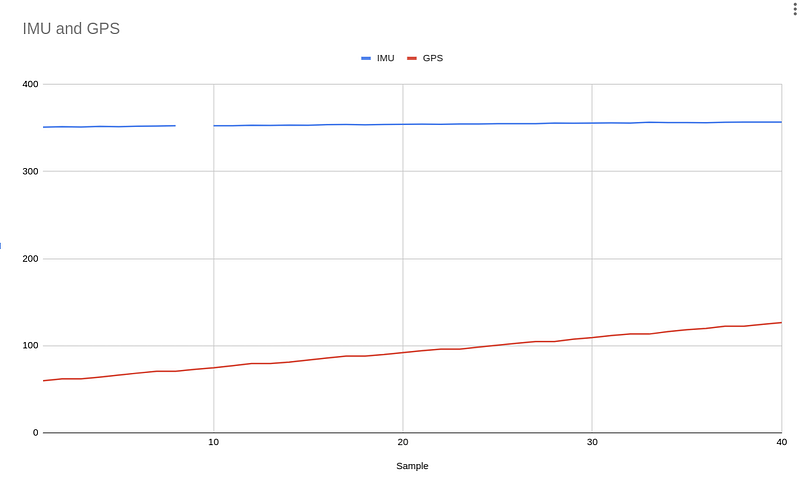
It is likely that correctly calibrating it would fix this, but I have not gotten there yet. Instead, I’m using a BNO055 to determine heading. At startup, the yaw value is zero, so I do a short forward drive and compute the bearing between the start and stop points to compute my current heading. It is then easy to adjust the BNO055’s yaw value to determine my actual heading in degrees.
Conclusions and Next Steps
It takes a bit of work to set up, but once working, the accuracy of the Zed F9P is absolutely stunning. I have the robot driving between waypoints using it using custom Python code on a Raspberry Pi, and it works very well. I’m experimenting with the very cool Greenzie boustrophedon path planner to compute coverage paths for the RTK guided mower I am working on with a good friend. Stay tuned! An article on how to use the path planner is coming soon.
I am excited to hear what you do with RTK GPS! If you’d like to follow along or chat, I’m @JRBowling on Twitter. Thanks!


