
Designing a New Drone — Part 1
Code Name: Magpie DS2 — The Objective
The Reefwing team have decided to design their own drone! The idea is that it will eventually utilise open source hardware and software can be used for STEM training in schools.
With this in mind, we have come up with the following criteria for our drone:
- The drone should be able to be constructed by students using a 3D printed airframe and a kit of parts provided.
- The drone should be modular, open source hardware and software and include an API to allow mission control.
- The design philosophy will be to provide the minimum functionality required to deliver the objectives.
- A secondary objective is to use a crowdsourcing campaign to help fund development and market the concept.
We will build a prototype based on commercially available parts and then design our own airframe and flight controller, once we have a design that flies. We want a modular design that we can add optional functionality to (e.g. FPV camera or GPS). The initial design will have space for these features but as we want to get something up and running as quickly as possible, it will only include the minimum components to get a flyable drone (i.e. air frame, battery, power distribution, ESC, flight controller, receiver, motors and propellers).
As part of the educational process we will document our design journey and explain the engineering choices that we make along the way.
Air Frame & Construction
For the prototype we will use a Martian II 220 mm frame design. This design is mostly used for racing quads but it is a nice light compact design and will provide a good starting point for us to iterate on.
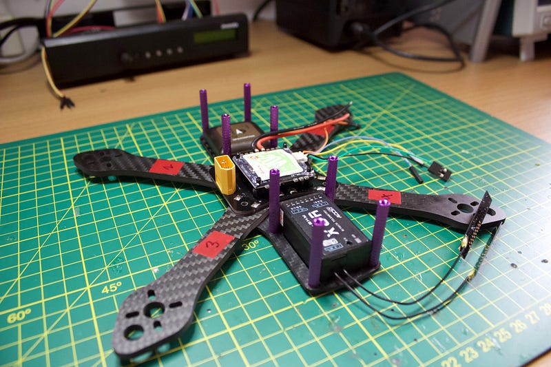
Frame construction is pretty straight forward. As shown in Figure 1, we labelled the front of the drone and motor number locations using electrical tape. This helps keep you oriented. Even though we won’t mount a GPS or FPV camera initially, we made sure that there was a spot at the front for it.
The first board attached to the frame is the Power Distribution Board. This makes it easy for us to distribute battery power to the ESC’s and flight controller. Regulated 5V and 3.3V supplies are available from the flight controller.
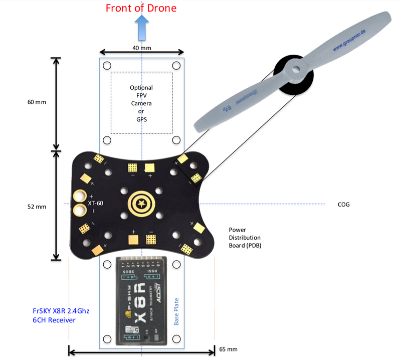
Once you have the arms attached to the bottom frame and the Power Distribution Board (PDB) mounted, you can add the quad 20A Electronic Speed Controller (ESC). The RacerStar ESC that I bought has mounting holes which line up nicely with the PDB. I assume that this isn’t a coincidence but I admit that I fluked it. Figure 2, provides an overview of what the bottom layer of the drone will look like when we are finished.
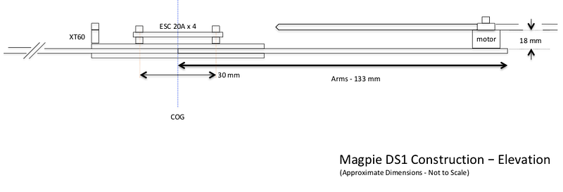
Using a stock Martian II frame, the available distance between the top and bottom layers is 30 mm and with the ESC in place we have already used 20 mm of that (Figure 3). Take this into account when you mount the Flight Controller board on top of the ESC.
Drones use an Inertial Measurement Unit (IMU) to determine the orientation of the air frame, these sensors may be a combination of accelerometers, gyroscopes, and magnetometers. When installing the flight controller board, make sure the arrow on the board points to the front of the drone. This ensures that the IMU is oriented correctly. You can tweak this in Betaflight configurator if you have to mount it in another orientation (YAW offset in the configuration tab, board sensor alignment — 90, 180, or 270 degrees usually).
When laying out the various modules on the air frame our aim is to keep the weight centred as much as possible. This makes level flight much easier to achieve for the flight controller.
Mounting the Motors
We need to mount the four brushless motors to work out the correct wire length to the ESC. My RacerStar motors came with two sets of M3 screws, 8mm and 6mm. The thickness of the frame arms is 4mm, so use the 6mm screws to ensure they don’t short out the motor coils. For now you can just do them up finger tight but eventually you will want to apply loctite to ensure that the motors don’t fall off mid flight (bad).
The RacerStar ESC can be programmed using the BLHeliSuite software on PC. With that we can reverse the motor direction but you need compatible Flight Controller software. For our purposes, it is probably simpler to just swap two wires if the motor is going in the wrong direction.
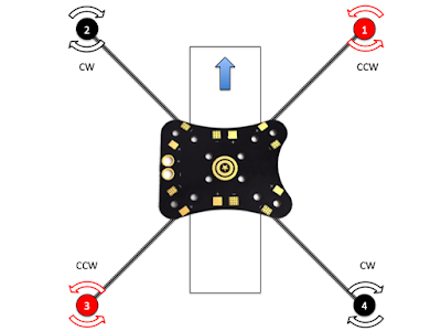
Our motors indicate their default rotational direction (clockwise or anticlockwise) by arrows on the top of the motor and different coloured propeller nuts. The black nuts rotate clockwise and the red nuts anticlockwise. To minimise the amount of work, you should mount the motors in the configuration shown in Figure 4.
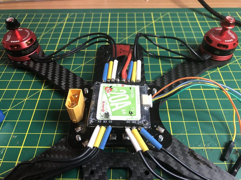
Once you have mounted the motors you can then wire them to the Quad ESC (Figure 5). While you are doing this, also solder the ESC battery connection to the appropriate pads (+ and -) on the Power Distribution Board and a connector to allow you to plug power into the flight controller. Make sure that you put the heat-shrink on before you solder the wires to the ESC and leave enough slack in the wires so that you can remove the board if required.
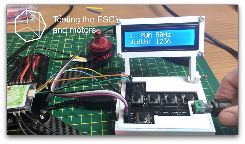
If you have a servo or ESC tester then now is a good time to test that everything is working and the motors are spinning in the desired direction (Figure 6). Next up we will look at mounting and testing the flight controller.
Flight Controller Firmware
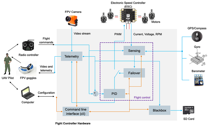
We have selected Betaflight as the flight controller firmware. It is open source and a fork of Baseflight and Cleanflight, focussed on flight performance. If required we could fork our own version or contribute to the Betaflight source code. Figure 7 illustrates a standard BetaFlight setup.
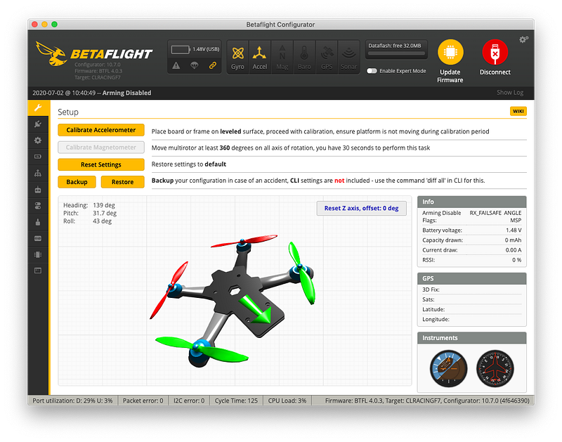
The flight controller firmware is the brains of the drone. The quality of this software and its tuning will determine how easy our drone is to fly. The Betaflight Configurator software (Windows, Mac or Linux) allows us to connect our PC to the flight controller hardware and upload the latest firmware version. It also allows us to configure, test and tune the software.
Flight Controller Hardware
As an interim Flight Controller we are using the CLRacingF7 MPU v2.1 MPU6000 (Figure 8). This flight controller is fully featured and uses a STM32 F7 MCU (i.e. heaps of grunt). The STM32 family of 32-bit microcontrollers are based on the Arm Cortex-M7 processor and are designed for high performance, real-time capabilities, digital signal processing, low-power / low-voltage operation, and lots of connectivity options.
The specifications of this board are impressive:
- MPU: STM32 F7 MCU
- IMU (Gyro): MPU6000
- Betaflight On Screen Display (OSD) capability
- Input voltage 2S — 8S (36V)
- BEC: 5V/3A and 3.3V/250mA
- Serial: 6 Full UART’s
- Supports FPV Camera Control (with necessary resistor and capacitor)
- VBAT Polarity protection and battery monitoring
- Built-in 32MB flash memory chip for Blackbox
- 4 Motor Control Outputs
- Includes a 32MB Blackbox flash chip
- Betaflight Target: CLRACINGF7, (comes preloaded with Betaflight)
The box from CLRACING also contains:
- 6x rubber grommets for soft mounting (2 spares)
- FC to 4in1 ESC ribbon cable (8-pin)
- a couple of spare headers (9-pin and 8-pin)
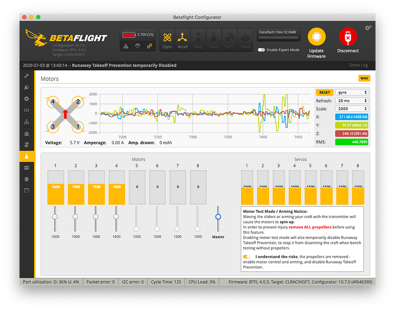
Before connecting the flight controller to the ESC’s, it is a good idea to check that it works with BetaFlight Configurator (Figure 9). You first need to download the configurator, and connect the flight controller to a computer USB port. Make sure that you use a USB cable which has the data pins connected, many of the charging cables don’t and you can waste a lot of time trying to diagnose this problem. We mark our cables to to assist with this issue.
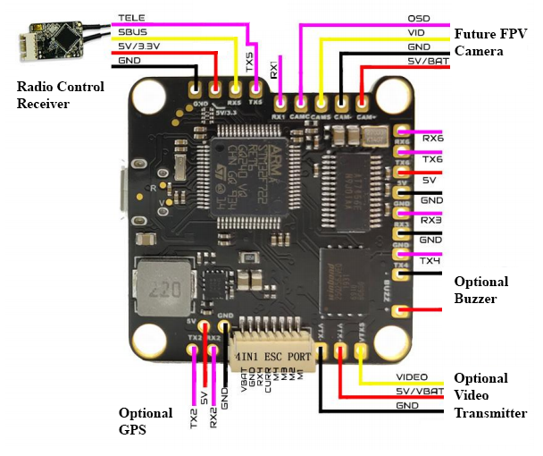
Connections to the flight controller board (Figure 8) are straight forward apart from the 4 in 1 ESC port. At this point we only need to install two connections:
- The four wires to the radio control receiver (SBUS, telemetry, 5V and GND); and
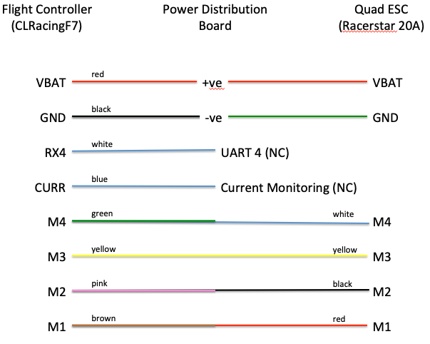
- The ESC Port (VBAT, GND, RX4, CURR, M4, M3, M2 and M1). Of course this is designed to match the corresponding port on a CLRACING 4 in 1 ESC and we are using the Racerstar which has different connections (GND, M4, M3, M2 and M1), so we will need to construct a wiring harness to suit. See Figure 10 for connection details.
The Racerstar Quad ESC comes with a couple of wiring harness which you can butcher or you can buy some JST 1.0 mm SH 6-Pin Connectors which match the ESC socket. Note that only 5 of these pins are used. Finding an 8 pin JST SH connector is much harder, so we will modify the cable that comes with the flight controller for the other end.
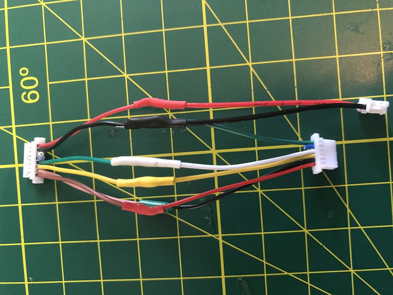
The completed harness is shown in Figure 11. In addition to the Flight Controller (FC) and ESC connections, we have drawn out a separate 2 pin JST connector which will provide VBAT (nominal 7.4V) voltage from the Power Distribution Board (PDB) and commoned up the GND connections. When designing the Nexgen PDB we will mount a 2 pins JST SH socket for this purpose. We may also add a Battery Elimination Circuit (BEC) if we don’t put this on the flight controller. The CLRacing FC provides a BEC which can provide 5V at 3A and 3.3V at 250mA but we wouldn’t want to pull 3A through the 1mm JST SH connection that is the only power connection for the FC. That connection will use a wire gauge size between 32 and 28 AWG, which shouldn’t be carrying more than 1A or things will get warm (reference)!
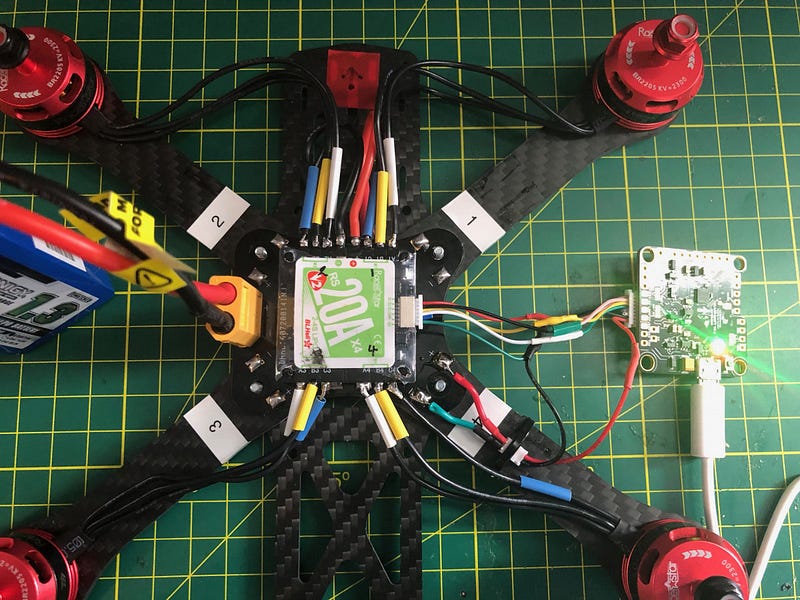
It is always a good idea to test before you do the final mounting. Figure 12 shows the flight controller connected to the ESC and powered by the battery using our new wiring harness. We will also connect up to BetaFlight Configurator again to make sure that the flight controller can talk to the ESC.
Before doing anything else, back up your flight controller settings. When you connect to BetaFlight, in the Setup tab (Figure 9), click on Backup and save the resulting JSON file somewhere safe. This way you can always restore the factory configuration if you mess something up. Alternatively you can type “dump” in the Command Line Interface (CLI) and save the output to a text file.
In the Configuration tab of the configurator you can change motor direction if required and select the ESC protocol. The default is ONESHOT125 and we will leave that as is for now. The Motors tab allows us to test the motors either via the flight controller or using the remote control (Figure 13). You need to click on the button acknowledging that you understand the risks before you can use the motor slider controls.
Power Distribution
All of the drones power comes from our 2S 1300 mAh Lithium Polymer battery (Figure 14).
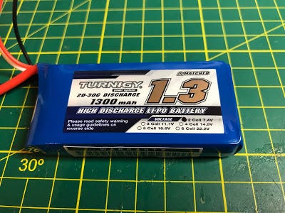
The specifications for our battery are:
- Minimum Capacity: 1300mAh
- Configuration: 2S1P / 7.4v / 2Cell
- Constant Discharge: 20C
- Peak Discharge (10sec): 30C
- Pack Weight: 81g
- Pack Size: 73 x 35 x 17mm
- Charge Plug: JST-XH
- Discharge plug: XT60
At 3.7V per cell our 2S battery will deliver a nominal 7.4V from the contacts on the power distribution board. The 2S indicates that we have two cells in series so the sum of the two cells voltage is the output voltage. As an aside, cells in parallel add to the batteries capacity (i.e. mAh) not voltage.
The CLRACINGF7 MPU V2.1 Flight Controller that we are using will provide 5V at 3A and 3.3V at 250mA. The modules we will need to power are:
- The CLRacingF7 MPU v2.1 MPU6000 Flight Controller.
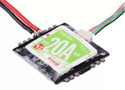
- The Racerstar BLHeli_S 20A Quad Electronic Speed Control — shown in Figure 15 (connects to the battery, receiver and the four motors). It doesn’t have a BEC (Battery Elimination Circuit) to provide a regulated supply. Supports the oneshot42, multishot, Dshot150 and Dshot300 ESC protocols.
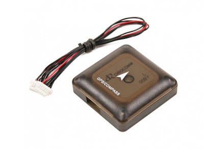
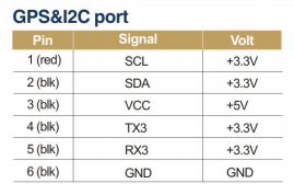
- The UBLOX Micro M8N GPS Compass Module — shown in Figure 16. This module expects a regulated 5V on VCC but control voltages are 3.3V (see Figure 17).
- The FrSKY X8R 2.4Ghz SBUS Receiver. The receiver will also need to be connected to the regulated 5VDC bus.
In Part 2 we will connect the remote control, pop on some propellers and see how she flies!
If you enjoyed this article and would like to help support my writing, then please subscribe to become a Medium Member. I will get a portion of your subscription fee and you get access to every story on Medium. Alternatively, you can buy me a coffee!


