74HC4067 — DeMux For Arduino
A multiplexer of this sort really just acts as a 16 to one 1 switch — Ardu_Serie # 83
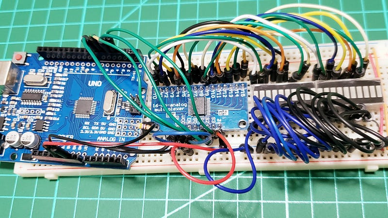
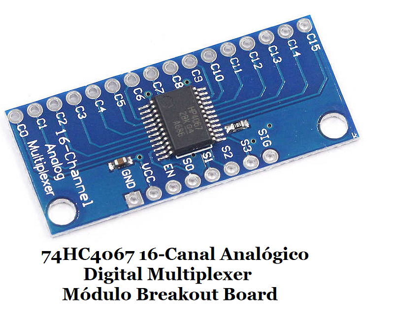
Hi, in this post we're gonna talk about this 74HC4067 board:
At this point, you should download the datasheet, as we refer to it through the course of the article
Specifications
(from https://www.sparkfun.com/products/9056)
- 2V to 6V operation
- “On” resistance: 70 Ohms @ 4.5V
- 6ns break-before-make @ 4.5V
- Wide operating temperature range: -55C to 125C
Here are the summary notes from my internet research:
Notes
-You can consider the 74HC4067 to be a digital replacement to those rotary switches that allow you to select one of sixteen positions;- 74HC4067 can operate on voltages between 2 and 6V DC (74HCT4067 it can only work on 4.5~5.5V DC);- The CD74HC4067 is a 16-Channel Analog Multiplexer/Demultiplexer;- CD74HC4067 is a super simple to use bidirectional mux that can make your life a lot easier;- It's a must having if you ate running out of pins to read an array of analog sensors;- Instead of upgrading your microcontroller, with this board you can to expand the I/O capabilities of your chosen microcontroller;- It’s an IC that can direct a flow of current in either direction from one pin to any one of sixteen pins;- The part itself is available in through-hole and surface mount versions;- can help multiply the amount of pins you have;- it is easy to connect to your arduino or other microcontroller;- it allows you to do is use 4 digital pins, to control the flow of one pin to 16 others;- It can actually be used in either direction, and even with serial or other digital interfaces;- A multiplexer of this sort really just acts as a 16 to one 1 switch;- 4 digital pins are used to set HIGH or LOW, in a binary fashion (0–15) to determine what pin “SIG” is connected to;- Bringing all 4 pins LOW would switch the CD74HC4067 to channel 0 (so SIG and C0 would be connected);- Bringing them all HIGH would switch it to 15 (so SIG and C15 would be connected);- The EN pin control when the mux is enabled or disabled; - The EN pin is a kill switch: pull it up to 5v to disable all channels, and ground it to enable them;- The CD74HC4067 is capable of more than reading analog signals, It can be uses in either direction;- So let us put this to good use:
- if you needed to control 16 relays, just connect SIG to 5v, and then be able to switch the 5v to one of 16 channel pins
- if you had 16 RFID readers that output serial just connect the SIG pin of the CD74HC4067 to digital 0 on the arduino (Serial RX pin) and the serial out of an RFID reader to one of the channels and be able to read from all 16 RFID readers;- Open you data sheet and consider:
- “DC Electrical Specifications” — minimum voltage that can be considered as a HIGH and the maximum for a
LOW depending on your supply voltage;
- “ON” resistance — that is the resistance in Ohms (O) between one of the sixteen inputs/outputs and the common pin;
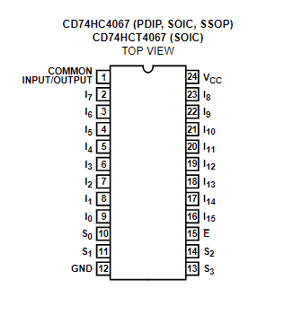
Consider the pinout diagram from the datasheet:
Pinout
How to Soldering
[TODO: VID SOLDERING GOES HERE!]
Fig 3. Lab video w/ HC4067
The Fritz
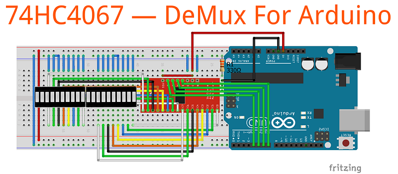
Demultiplexer is a combinational logic circuit designed to switch one common input line to one of several separate output line;Multiplexer is a combinational logic circuit designed to switch one of several input lines to a single common output line;The Code
The video
[TODO: VID 1 GOES HERE!]
Fig 5. Lab video w/ HC4067
Credits & References
SparkFun Analog/Digital MUX Breakout — CD74HC4067 by https://www.sparkfun.com
Datasheet High-Speed CMOS Logic 16-Channel Analog Multiplexer/Demultiplexer by Texas Instruments
The Multiplexer by https://www.electronics-tutorials.ws
The Demultiplexer by https://www.electronics-tutorials.ws