5G Core Part 4 — Dedicated QoS Flow and PDU Session Modification

Introduction
In the 5GC Part 2 — PDU Session and Call Flow, I talked about the PDU Session Establishment for a UE (e.g., a 5G Smart Phone) to a Data Network (DN) for data traffic exchange. I also showed all the important Information Elements (IEs) exchanged during the PDU Session Establishment call flow described in the 3GPP’s Procedures for the 5GS TS 23.502’s UE-requested PDU Session Establishment for non-roaming and roaming with local breakout with Wireshark traces. The following shows the UE that has successfully established a PDU Session with a Default QoS Flow to a Data Network Name (DNN), voice_video.acme1.com on a 5G Mobile Gateway:
SUPI 302990001003201
 DNN = voice_video.acme1.com
 UL APN AMBR = 20.00 Mbps
 DL APN AMBR = 30.00 Mbps
 UE IPv4 address = 10.10.101.1

NF Service nsmf-pdusession
 NF Role = producer
 resourceUrl = http://172.24.0.1:65535/nsmf-pdusession/v1/sm-contexts/00011100
 Service Instance = Nsmf_PDUSession

NF Service namf-comm
 NF Role = consumer
 Service Instance = Namf_Communication

NF Service npcf-smpolicycontrol
 NF Role = consumer
 resourceUrl = http://172.24.0.10:9000/npcf-smpolicycontrol/v1/sm-policies/302990001003201_1
 Service Instance = Npcf_SMPolicyControl
 PCF Triggers = QOS DEF_BR_QOS PRA_REPORTING_AREA SCNN

NF Service nudm-sdm
 NF Role = consumer
 resourceUrl = http://172.24.0.10:8000/nudm-sdm/v1/imsi-302990001003201/sdm-subscriptions/302990001003201_0
 Service Instance = Nudm_SubscriberDataManagement

<# Other Service based Interface (SBI) Info skipped #>

Default QoS Flow
 5QI/ARP = 9/11  QFI = 9
 QNC = Disabled
 RQI = Disabled

UP Type  Original PSA
UP Sx-N4 Ctl V4 = 192.168.41.3
CP Sx-N4 Ctl V4 = 192.168.41.1
CP Sx-N4 Seid  = 0x11100
UP Sx-N4 Seid  = 0x11100
gNb N3 Data TEID     = 0x10000001
gNb N3 IPv4 Address  = 10.20.31.10
UP N3 Data TEID      = 0x40034105
UP N3 IPv4 Address   = 10.20.31.3
A 5G Mobile Gateway can comprise many 5G Control and User Plane Network Functions but usually, they implement the SMF (Session Management Function) and the UPF (User Plane Function).
The 5G Mobile Gateway shows that the UE’s PDU Session has a Default QoS Flow of 5QI = 9 and ARP = 11. The UL (Uplink) and DL (Downlink) APN AMBRs for non-GBR traffic to the DNN, voice_video.acme1.com are 20Mbps and 30Mbps respectively.
The non-GBR (i.e., 5QI = 9) Default QoS Flow of the PDU Session allows the UE to exchange best-effort traffic with the DN such as surfing the Internet. More importantly, it enables the UE to create additional Dedicated QoS Flows to support more QoS-demanding traffic such as voice, video, autonomous driving, and gaming traffic etc…
The UL N3 UPF’s IP address is 10.20.31.3 and the Core Network GTP-U Tunnel ID (CN_TEID) for the UE is 0x40034105. The DL N3 gNB’s IP address is 10.20.31.10 and the Access Network GTP-U Tunnel ID (AN_TEID) for the UE is 0x10000001. Unlike 4G LTE where each UE’s bearer has its own pair of UL and DL GTP-U TEIDs to setup and release, in 5GS, all QoS Flows for a UE for a given Access Point Name (APN) or DN use the same pair of UL and DL GTP-U TEIDs. We will see later that when the UE establishes a Dedicated QoS Flow (i.e., focus of this article) in additional to its Default QoS Flow (i.e., focus of the 5GC Part 2 article), all the QoS Flows or data traffic travel on the same GTP-U Tunnels using the same pair of UL CN and DL AN GTP-U TEIDs.
The Service Base Interface (SBI) section shows the resourceUrl for each of the UE’s SBIs stored at the SMF of the 5G Mobile Gateway. For example, to access the UE’s information stored at the UDM, the 5G Mobile Gateway’s SMF needs to formula a ReST (REpresentational State Transfer) message over HTTP to the UDM at the http://172.24.0.10:8000/nudm-sdm/v1/imsi-302990001003201/sdm-subscriptions/302990001003201_0 using the HTTP GET operation. The UDM will then response with the UE’s info it stored in its database in the HTTP response. We will come back to the SBI, and HTTP operations in more details later.
The focus of this article is about the procedures and information exchange for modifying an existing PDU Session to setup a Dedicated QoS Flow to enrich the 5G experience of a UE in addition to its best-effort Default QoS Flow created after the PDU Session is established. Similar to the Part 2 of this series of 5G articles, we will use the 3GPP 5GS Procedures TS 23.502 to illustrate the setup of a Dedicated QoS Flow for a PDU Session. A corresponding Wireshark trace captured in a 5GC home lab using Github’s jdegre/5GC_APIs is also used to illustrate the procedures. I will write a separate article about setting up a 5GC home lab with a single Linux PC in my future articles.
5G QoS Model
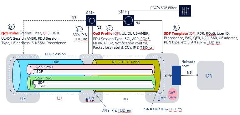
Using the below 5GS QoS diagram from the Part 2 of this series of 5G articles, the following are the minimum IEs that the UE, gNB, and UPF needed for establishing a Dedicated QoS Flow between the UE and the DN:
- the UPF needs to know the IP address and the Access Network (AN) GTP-U TEID for the UE to forward DL traffic to the UE. The gNB also needs to know the IP address and the Core Network (CN) GTP-U TEID for the gNB to forward UL traffic to the DN. We will verify that both the Default and the Dedicated QoS Flows use the same pair of UL and DL GTP-U TEIDs
- the UE, gNB and UPF need to have all the QoS details for the Dedicated QoS Flow such as the desired 5QI, ARP, Precedence, Packet Filters for SDF binding, GBR, MBR etc…
- the UL Packet Filters for the UE map its UL traffic onto the Dedicated QoS Flow. The UPF also needs to have the UL Packet Filter to verify that the UL traffic carried by the Dedicated QoS Flow is correct or the UPF will drop the UL traffic and not forward it to the DN
- the DL Packet Filters for the UFP map DN’s DL traffic to the Dedicated QoS Flow
UE-Initiated and Network-Initiated PDU Session Modifications
The following shows the PDU Session Modification Call Flow for creating Dedicated QoS Flows based on the 3GPP Procedures for the 5GS TS 23.502’s Figure 4.3.3.2–1: UE or network requested PDU Session Modification (for non-roaming and roaming with local breakout).

The 3GPP messages 1a to 1f of the above 3GPP Call Flow highlights two kinds of PDU Session Modification methods for creating a Dedicated QoS Flows for a UE such as the:
- UE-Initiated PDU Session Modification (3GPP Message 1a)
- Network-Initiated PDU Session Modification (3GPP Messages 1b to 1f )
In this article, we will focus on the Network-Initiated PDU Session Modification method, PCF-initiated SM Policy Association Modification (i.e., 3GPP Message 1b). An example of this scenario is that the UE uses its default QoS Flow to signal, say a voice server on the DN. The voice server then calls the Application Function’s SBI to request the PCF to send a Npcf_SMPolicyControl_UpdateNotify (3GPP message 1b) to the SMF for establishing the Dedicated QoS Flow for the UE to the DN.
In order for the Dedicated QoS Flow to be able to support, say the UE’s voice traffic end-to-end, all the 5GS subsystems such as the UE, gNB, and UPF along the data path need to be consulted and agreed upon to support the creating of this voice Dedicated QoS Flow. Therefore, the PDU Session Modification procedures are simply about having the SMF to consult the UE, gNB and UPF via the QoS-rules, QoS-Profile and SDF Template respectively to make sure that each subsystem can support the Dedicated QoS Flow for the UE to the DN before the SMF can finalize the Dedicated QoS Flow creation in the above 3GPP Call Flow (i.e., 3GPP Messages 1b to 8b).

In order to simplify the explanation of the above call flow for modifying an existing PDU session for a UE to a DN to create a Dedicated QoS Flow in addition to its existing Default QoS Flow for more QoS demanding traffic such as voice, we are going to divide the above Call Flow from the 3GPP messages 1b to 8b into 3 different sections as follows:
- Section A — Network (or PCF) Initiated PDU Session Modification Request to the SMF (i.e., 3GPP messages 1b to 3c)
- Section B — PDU Session Modification for the gNB and the UE (i.e., 3GPP messages 3b to 5)
- Section C — PUD Session Modification for the UPF (i.e., 3GPP messages 6 to 8b)
Section A — Network (or PCF) Initiated PDU Session Modification Request to the SMF
Both the UE-Initiated and the Network-Initiated PDU Session Modifications support the following types of PCC (Policy and Charging Control) for creating Dedicated QoS Flows for a UE:
- Predefined PCC — The PCF sends only the name of the Predefined PCC to the SMF. If the SMF and the UPF have the corresponding QoS and charging configuration matching the predefined PCC, the SMF will coordinate the setup of the Dedicated QoS Flow based on the predefined PCC’s configuration for the UE to the DN
- Dynamic PCC — The PCF sends all the QoS requirements such as the GBR, MBR, 5QI, Packet Filters for SDF binding and charging etc… in a PCC to the SMF. We call it Dynamic PCC. The SMF will coordinate the setup of the Dedicated QoS Flow for the UE to the DN. There is no need to pre-config any UE’s QoS info the SMF and the UPF to support the Dynamic PCCs
3GPP Message 1a / Frame 1— Initiate PDU Session Modification
The following shows the first message, 3GPP message 1b (Wireshark Frame 1) for the Network-Initiated PDU Session Modification using a Predefined PCC called prb_GBR_voice to create a Dedicated QoS Flow for the UE to the DN, voice_video.acme1.com:
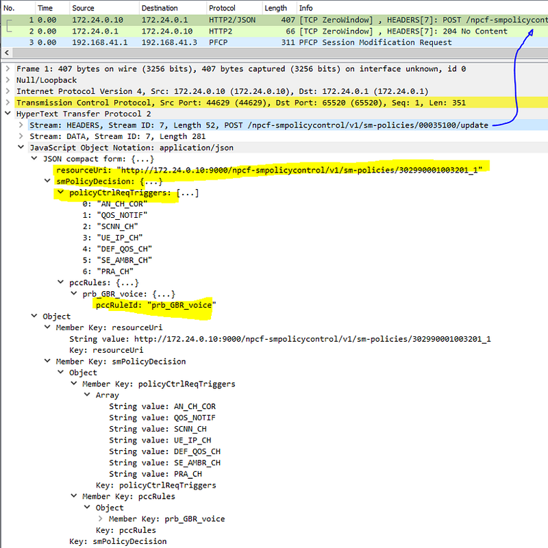
The PCF (SBA service producer) with IP address 172.24.0.10 notifies the SMF (SBA service consumer) with IP address 172.24.0.1 via the PCF’s service, Npcf_SMPolicyControl_UpdateNoify for the creation of the predefined PCC, prb_GBR_voice for the UE with the SUPI 302990001003201. The PCF notifies the SMF for the event because the SMF has subscribed to the PCF to receive notification from the PCF. No other QoS or charging information such as 5QI, or Packet Filters etc… are passed by the PCF to the SMF as it is expected that all these QoS information have already been pre-provisioned at the SMF and the UPF.
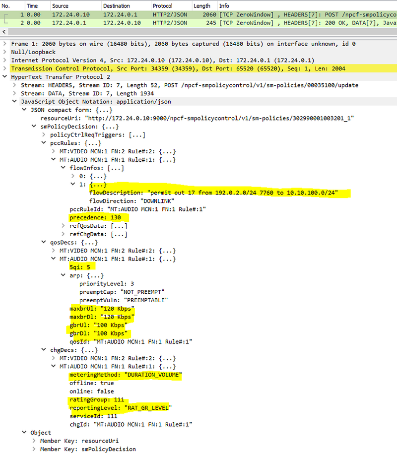
For comparison, the following shows the PCF notifies the SMF with a Dynamic PCC to create a Dedicated QoS Flow. In this case, all the QoS parameters such as the 5QI and Packet Filters for SDF binding (permit out 17 from 182.0.2.0/24) etc.. are provided by the PCF to the SMF:
Under the 5G Service Base Architecture (SBA), all control plane Network Functions (NFs) such as the PCF or the SMF can be a service consumer and a service producer depending which Service Based Interface (SBIs) or APIs are being used. The following shows the PCF’s SBIs defined in the 3GPP Session Management Policy Control Service; Stage 3 (3GPP TS 29.512 version 15.2.0 Release 15):
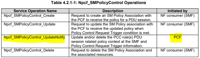
For example, the SMF subscribes to the PCF’s Npcf_SMPolicyControl_UpdateNotify service (i.e., SMF is the service consumer for this PCF’s SBI) and the SMF will be notified by the PCF (i.e., service producer) when certain events happened such as the PCF is being requested by an AF to create a Dedicated QoS Flow for a UE. Similarly, the SMF can request the PCF’s Npcf_SMPolicyControl_Create service to create an SM Policy Association for a UE on the PCF so that the PCF can manipulate the state of the UE .
When we say a service consumer NF requests or subscribes to a SBA service producer NF, we are referring to the operations where the SBA service consumer NF uses the HTTP protocol to transport a Representational State Transfer (ReST) formatted message to the service producer NF to Create, Read, Update or Delete (CRUD) some resources referenced by the resourceUrl object in the HTTP packet. The CURD operations on the resources are mapped to the following HTTP Operators:
- Create = HTTP POST
- Read = HTTP GET
- Update = HTTP PUT/PATCH
- Delete = HTTP DELETE.
In the 3GPP Message 1b (Wireshark Frame 1), the service producer PCF notifies the SMF via the HTTP Header — POST /npcf-smpolicycontrol/v1/sm-policies/00035100/update, which is in effect the Npcf_SMPolicyControlUpdateNotify SBI in the 3GPP specification to request the SMF to setup a Dedicated QoS Flow for the UE with the SUPI 302990001003201. This shows that the the 3GPP specification shows only the semantic of an NF’s SBIs but the actual message formatting over the wire illustrated by Wireshark is different.
Beside the pccRuleId: prb_GRB_voice attribute in the 3GPP Message 1b (Wireshark Frame 1), there are many other attributes defined in the smPolicyDecision object. To fully understand the structure and meanings of each of the objects and the attributes inside a SBA message, one will need to lookup to the corresponding 3GPP’s technical specifications such as the 3GPP’s Session Management Policy Control Service; Stage 3 (3GPP TS 29.512 version 15.2.0 Release 15) in this case. For example, the function of the policyCtrReqTrigger and the meaning of the PBA_CH in the WireShark Frame 1 can be found in this 3GPP Technical Specification’s Section 4.1.5 Policy Control request trigger and Section 5.6.3.6 Enumeration: PolicyControlRequestTrigger respectively.
3GPP Message 2a / Wireshark Frame 3 — Activate predefined PCC
Once the PCF notifies the SMF about the SMPolicyControl update for the UE in the 3GPP Message 1b / (WireShark Frame 1), the SMF will update the UPF over the N4 PFCP interface as shown in the 3GPP message 2a (Frame 3):

While the PCF only specifies the attribute pccRuleId: prb_GBR_voice in the 3GPP Message 1b (Wireshark Frame 1) without any other QoS and charging parameters, the SMF can actually fill in all the QoS and charging parameters for the UPF using its pre-configured info for the predefined PCC, prb_GBR_voice. This shows that the SMF and the UPF need to be pre-configured to support predefined PCC, prb_GBR_voice. If the SMF and the UPF had not been pre-configured with the predefined PCC’s details or they did not have resources to support the PDU Session Modification, the UPF would return a Failure Cause, Resource_Not_Allocated to the SMF in the N4 PFCP Reply.
Note that the SMF controls the IP address assignment for the UE for the given APNs. The SMF assigns the IP address 10.10.101.1 to the UE and it is included in the PFCP message to the UPF.
The 3GPP Message 2b (Wireshark Frame 4) shows that the UPF’s reply to accept the N4 PFCP Request from the SMF. The same UPF’s N3 IP address 10.20.31.3 and the CN GTP-U TEID 0x40034105 used for the Default QoS Flow for the UE are returned to the SMF. Under the non-roaming scenario, all the QoS Flows for a UE use only one pair of CN GTP-U TEID for UL and AN GTP-U TEID for DL for the UE’s traffic for a given APN. That is the reason why 5G is more suitable for short-live connections for IoT devices as compare to 4G LTE where each 4G bearer needs a separate pair of AN and CN GTP-U TEIDs to be setup and teardown.
3GPP Message 2b / Wireshark Frame 4 — predefined PCC Activation Successful
In the 3GPP Message 2b, the UPF replies to the SMF that the activation of the pre-defined PCC, prb_GBR_voice is successful.

Section B — PDU Session Modification for the gNB and the UE
Now that the SMF knows the UPF accepts the Dedicated QoS Flow creation with the predefined PCC, the SMF still needs to find out whether the UE and the gNB can also support the Dedicated QoS Flow creation. The SMF therefore calls the AMF’s namf-comm service in the 3GPP message 3b (Wireshark Frame 5) to pass the QoS info of the Dedicated QoS Flow to the UE and the gNB using the N1's QoS-Rules and the N2's QoS-Profile respectively.
Message 3b / Frame 5 — Request gNB and UE to support PDU Session Modification
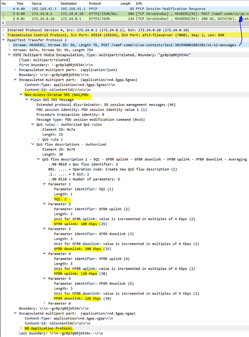
The 3GPP N1 interface is defined between the UE and the AMF (via gNB) and the protocol used for the interface is called the Non-Access-Stratum (NAS) NAS. The NAS protocol provides mobility and session management to ensure the UE is in contact with the 5GC during UE roaming.
Most gNBs are designed with Control and User Plane Separation (CUPS) in 5G where the gNB’s CP traffic terminates onto the AMF (i.e., 3GPP N2 interface) and the gNB’s UP GTP-U traffic terminates onto the UPF (i.e., 3GPP N3 interface). The CP protocol ran over the N2 interface between the gNB and the AMF is called the Next Generation Application Protocol (NGAP). The NGAP provides the control plane signaling between the NG-RAN node and the AMF.
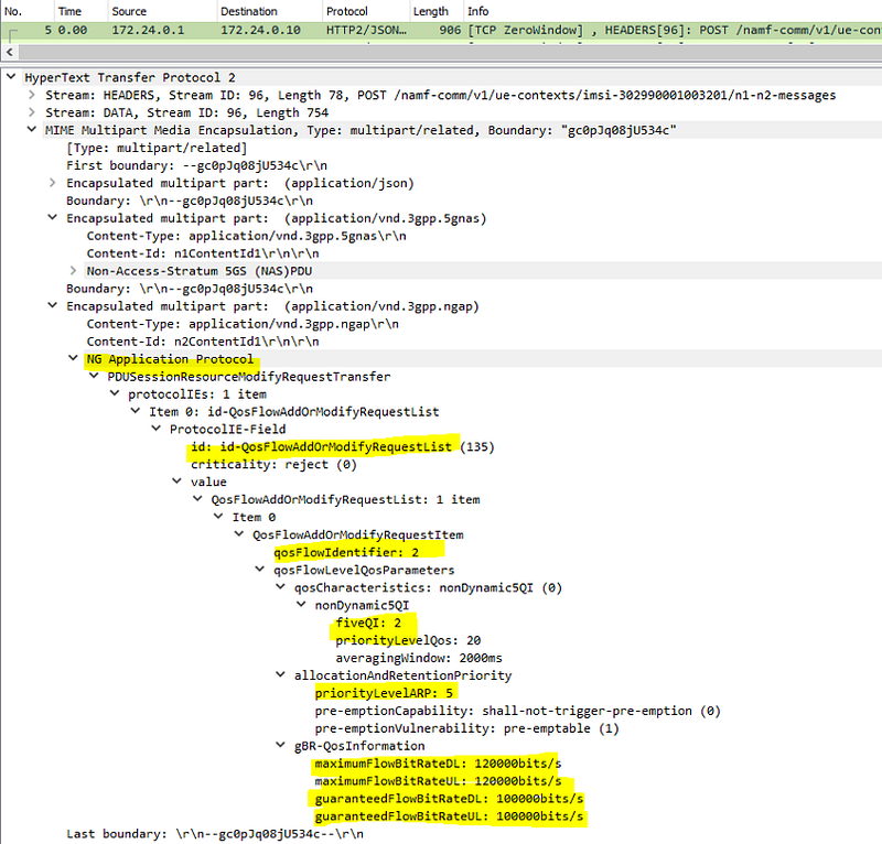
Both the N1 and the N2 messages from the AMF to the UE and the gNB respectively are about the QoS characteristics of the GBR Dedicated QoS Flow with 5QI = 2, GBR = 100Kbps and MBR = 120Kbps etc…
Similar to the PCF’s Npcf_SMPolicycontrol service operation in the 3GPP message 1b (Wireshark Frame 1), the service consumer SMF calls the service producer AMF for its Namf_Communication/N1N2MessageTransfer service.
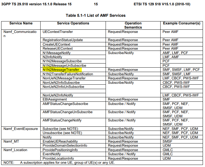
The operations of this service can be found in the Access and Mobility Management Services; Stage 3 (3GPP TS 29.518 version 15.1.0 Release 15).
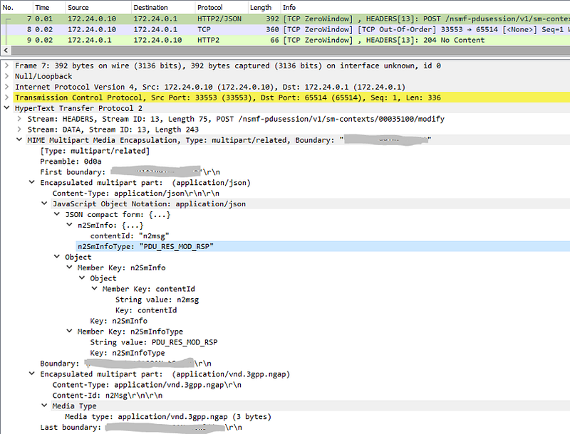
The 3GPP Message 7a (Wireshark Frame 7) contains the reply from the gNB (and the UE) about the Dedicated QoS Flow creation. The AMF advises the SMF that the UE and the gNB can support the Dedicated QoS Flow setup.
Messages 7a (Wireshark Frame 7) — gNB and UE can support PDU Session Modification
Section C — PDU Session Modification for UPF
At this point, the SMF knows that the UE, gNB and UPF can support the GBR Dedicated QoS Flow establishment to support the UE’s voice traffic and thus the SMF now uses the N4 PFCP session for the UE to advise the UPF to finalize the Dedicated QoS Flow establishment for the UE. Note that the gNB’s IP address and the AN GTP-U TEID for the UE’s DL traffic for the Dedicated QoS Flow are same as the Default QoS Flow.
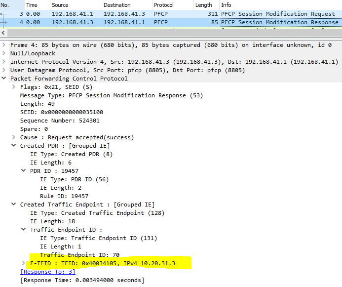
Message 8a / Frame 11 — Finalize Dedicated QoS Flow Creation
The 3GPP Message 8a (Wireshark frame 11) shows the PFCP Modification Request sent from the SMF at 192.168.41.1 to the UPF at 192.168.41.3 over the N4 PFCP interface:


After the SMF receives the PFCP reply from the UPF in the 3GPP Message 8b, the Dedicate QoS Flow for the UE’s voice traffic is successfully setup on the 5G Mobile Gateway as follows:
SUPI 302990001003201
 DNN = voice_video.acme1.com
 UL APN AMBR = 20.00 Mbps
 DL APN AMBR = 30.00 Mbps
 UE IPv4 address = 10.10.101.1

<# Default QoS Flow information skipped #>

PCC Rule Name : pr_GBR_voice
 PCC Rule ID : 38979 PCC Precedence : 12
 5QI = 2
 UL MBR (kbps) = 120 DL MBR (kbps) = 120
 UL GBR (kbps) = 100 DL GBR (kbps) = 100
 Filter id : 0 Filter direction : BiDir
 Filter protocol : udp (17)
 Local address : any
 Local ports : 34501–34509
 Remote addr : any
Now, the UE has both the Default QoS Flow for best-effort Internet traffic and a Guaranteed Bit Rate (GBR) Dedicated QoS Flow for voice traffic to enrich its 5G network experience.
Conclusion
The principle of operations for setting up a 5G’s Dedicated QoS Flow is very similar to a 4G’s Dedicated Bearer. The 4G Control Plane protocols such as the GTP-C for MME and the Diameter for PCRF/PGW are being replaced by a unified SBA Control Plane protocol based on HTTP2 and ReST messaging in 5G.
You can follow me on www.medium.com for all my current and future articles on 5G Core, IP/MPLS and software technology.