5G Core Part 2 — PDU Session Establishment and Call Flow

Introduction
Part 1 of this series of 5G articles provides a quick overview of the 5G System (5GS) particular its 5G mobile core (5GC). It briefly describes what are SMF, AMF, PCF, QoS Flow, SDF, DRB, and AN_Tunnel and CN_Tunnels etc…. It also shows how a UE (User Equipment such as a 5G Smartphone) can establish a PDU session via the new 5G new radio (gNB) to a Data Network (DN) for traffic exchange. For brevity, we left a lot of details out from the article but did highlight some missing details or questions in the Summary Section at the end of the article.
This is Part 2 of this series of 5G articles where we will examine the UE-Requested PDU Session Establishment in details with Wireshark traces to illustrate the messages and the parameters exchanged among the UE, gNB, AMF, SMF and UPF etc… for establishing a PDU Session between a UE and a DN.
When a UE establishes a PDU session to a DN for traffic exchange, a non-GBR (non Guaranteed Bit Rate) Default QoS Flow without any Uplink (UL) or Downlink (DL) Packet Filters is also setup to carry the UE’s traffic to the DN and vice versa. Additional GBR and non-GBR Dedicated QoS Flows can be setup for the UE to the DN to support more QoS demanded network applications such as voice and video via the UE-Initiated or the Network-Initiated PDU Session Modification Request to the SMF. For example, a UE having a PDU Session to a DN can use its Default QoS Flow to signal a video server in the DN to call to the Application Function (AF) to trigger the PCF in the 5GC to initiate a Network-Initiated PDU Session Modification Request to the SMF to create a new GBR Dedicated QoS Flow for video conferencing with the QoS requirements such as:
- 5QI = 3 (GBR QoS Flow)
- ARP = 8
- Packet Filters to match UL and DL UDP port 1234
- latency < 10ms
- UL/DL bandwidth = 2 Mbps GBR
- etc…
For brevity, this article concentrates only on the Default QoS Flow setup. For more information about the Dedicated QoS Flow setup, please refer to the article, 5G Core Part 4 — PDU Session Modification and Dedicated QoS Flow for details.
PDU Session Establishment Message Sequence
In order for a PDU session and a Default QoS Flow to be setup along the user path involving the UE, gNB and UPF to exchange traffic (i.e., Service Data Flows or SDFs) with the DN, a lot of IEs (Information Elements or parameters) are needed to exchange among the AMF, SMF, UE, gNB and UPF as shown in the below diagram:

The SMF sends the following QoS constructs to different 5G subsystems for the UE’s PDU Session establishment to the DN:
- SDF Template to the UPF via the SMF/UPF’s N4 PFCP interface
- QoS Profile to the gNB via the AMF using the AMF/gNB’s N2 interface
- QoS Rule to the UE via the AMF using the AMF/UE’s N1 interface over the gNB/UE wireless connection
Collectively, the SDF Template, QoS Profile and QoS Rule for the UPF, gNB and UE respectively try to setup the PDU Session and the Default QoS Flow for the following traffic QoS operations:
- Classification — Classify and bind the UE’s Uplink (UL) and Downlink (DL) traffic to the appropriate Default and Dedicated QoS Flows that are setup with different 5QIs or QoS characteristics in term of latency, scheduling priority, packet lost etc.. In the DL direction, the UPF relies on the Packet Filters setup in the PDU Session Modification procedures for Dedicated QoS Flows to bind the DL traffic to the appropriate QoS Flows. For the UL direction, the UE performs this bearer binding operations
- Queuing, Rate Policing and Scheduling — Enforce GBR and non-GBR UE and DN traffic such as UL/DL bandwidth, latency, traffic priority etc… for the QoS Flows
- Marking/Remarking — The UPF marks the mobile traffic (e.g., set each packet’s DSCP) when the UL traffic leaves the UFP to the DN. This is also applicable for the the UPF to send DL traffic to the gNB over a Radio Area Network (RAN) so that the priority of the traffic is honored end-to-end from the UE through the DN and vice versa
The following shows the most basic PDU Session Establishment procedures for non-roaming and roaming with local breakout described in the 3GPP’s Procedures for the 5G System TS 23.502 Version 16.4.0.
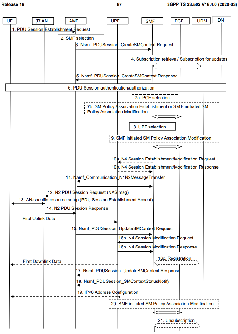
A detailed description of each of the above messages can be found in the 3GPP specification and thus they are not repeated in here. Rather, we will use a Wireshark trace to illustrate a few key messages in the above 3GPP Call Flow to reinforce the relationship and message exchange among the Service Based Architecture (SBA) Control Plane NFs such as the AMF, SMF and PCF etc… for setting up a PDU session for a UE to a DN.

We are dividing the above 3GPP Call Flow into multiple 3GPP message groups for ease of explanation.
A) 3GPP Messages 1 to 7 — UE Subscription Verification and Authorization
In the 3GPP Message 1, the UE sends a PDU Session Establishment Request to the AMF via the gNB to start the PDU Session Establishment procedures.
By the way, a UE will not send its Subscriber Permanent Identifier (SUPI) over the air to the gNB for security reason. Instead, it sends the encrypted version of the SUPI called the Subscriber Concealed Identifier (SUCI) to the gNB. The AMF then uses the UE’s encryption key stored in the UDM to decrypt the SUCI to the SUPI so that trusted NFs in the SBA of the 5GC control plane can use the SUPI for authentication and authorization.
In the 3GPP Message 3, the AMF invokes the SMF’s Nsmf_PDUSession_CreateSMContext Request SBI service to pass the UE’s info to the SMF for it to coordinate the UE’s PDU Session establishment to the DN.

There are many ways to setup a 5GC home lab (e.g., jdegre/5GC_APIs) to generate and capture 5G SBA messages using Wireshark . I will have a separate article about setting up a 5GC home lab with a single Linux PC.
The following shows the Nsmf_PUDSession_CreateSMContext Request SBI in the 3GPP Message 3 from the AMF (10.10.7.71) to the SMF (10.30.90.1). Due to the amount of info contained in the Nsmf_PUDSession_CreateSMContext Request SBI message, it takes two HTTP2 packets (Frames 612 and 614) to carry the SBI message as follows:


The following shows some of the UE’s supplied Information Elements (IEs) where the AMF passes to the SMF via the Nsmf_PDUSession_CreateSMContext Request SBI in the 3GPP Message 3:
- UE’s SUPI (Subscriber Permanent Identifier)
- target DNN (Data Network Name)
- anType (Access Network Type)
- sNssai (Single Network Slice Service Assistance Identifier)
- dnn (data network name that the UE wants to establish the PDU session)
- etc…
Using the 3GPP Message 3 as an example, the AMF’s SBI message uses the HTTP2 protocol to transport a Representational State Transfer (ReST) formatted message with the HTTP header POST /nsmf-pdusession/v1/sm-contexts to the SMF. The HTTP POST operator indicates that it is a Create operation. In other words, 3GPP 5G control plane specifications shows the semantics of the 3GPP SBA NFs’ SBI request/response and subscribe/notify services but the actual SBI services or API Calls are manifested over the wires in the form of ReST formatted messages with the HTTP operators POST, GET, PUT, and DELETE correspond to the SBI’s Create, Read, Update and Delete (or CRUD) operations.
In the 3GPP Message 4, the SMF retrieves the UE’s subscription information from the UDM and optionally, call the PCF to see whether the carrier has any policies implemented to augment the default UE’s subscription in the UDM such as to upgrade the UE’s DL speed from 100Mbps to 300Mbps for a special promotion for loyal customers etc…
In the 3GPP Message 5, the SMF sends the Nsmf_PDUSession_CreateSMContext Response to the AMF to confirm the PDU Session Management Context is successfully created for the AMF and the SMF for the UE’s PDU Session Establishment Request:

In the above Nsmf_PUDSession_CreatSMContext Response message, the SMF includes the location — http://10.30.90.1:65333/nsmf-pdusession/v1/sm-contexts/0001c100 to the AMF. This is the resourceUrl for the AMF to manipulate the PDU Session of the UE on the SMF. For example, in the Network-Initiated PDU Session Modification, the PCF can send the Npcf_SMPolicyControl_UpdateNotify() Notification to the SMF with the UE’s resourceUrl to create a new Dedicated QoS Flow for the UE in addition to the UE’s Default QoS Flow etc…
B) 3GPP Messages 8 to 10 — PDU Session Setup for UPF
Now that the AMF and the SMF have the Session Management (SM) Contexts created for the UE’s PDU Session but we have not yet set up the UE, gNB and UPF to support the UE’s PDU Session.
Message 10a (Wireshark Frame 733) shows the SMF sends the N4 Packet Forward Control Packet (PFCP) Session Establishment/Modification Request over the N4 interface to the UPF for it to support the UE’s PDU Session:

The UL MBR (Maximum Bit Rate) 20000Kbps and the DL MBR 30000 Kbps are the UL and DL APN AMBR for the non-GBR traffic for the UE’s PDU Session.
The following IEs are included in the PFCP Session Establishment request to the UPF for UE traffic classification, queuing, scheduling, and marking/remarking purposes. Note that the above IEs are usually come in pair for both the UL and DL traffic respectively.
PDR (Packet Detection Rule)
- Packet Detection Information (PDI) to classify DL traffic using 5-tuple to map the DL traffic (i.e., SDF) to a QoS Flow (i.e., SDF Binding) within the PDU Session. The UL PDI is used to verify that the UL traffic from the UE is mapped correctly to an appropriate QoS Flow or the UPF will drop the UL traffic to the DN
- Pointers to the FARs, QERs, URRs and BARs
- Precedence to determine the order of a PDR and its associated FARs, QERs, URRs and BARs are evaluated
FAR (Packet Forwarding Rule)
- Service chaining’s packet processing operations such as forward, duplicate, send to Control Plane etc…
- QoS marking (e.g., DSCP) to the DN and gNB
QER (QoS Enforcement Rule)
- Enforce traffic such as their GBR and the non-GBR bandwidth and latency. For example, the DL APN AMBR is set to 30Mbps for the DN. Any non-GBR traffic from the DN over 30Mbps is dropped by the UPF
URR (Usage Report Rule)
- Usage reporting from the UPF to the SMF. The SMF can forward the usage info to the PCF for it to apply any over-usage policies for the UEs
BAR (Buffer Action Rule)
- Support buffering DL traffic for idle UEs before the UEs are woke up by the SMF/AMF to receive the DL traffic
QFI (QoS Flow Identifier) is set to 9. Note that this SMF generated QFI value is being sent to the UPF, gNB and UE for a given QoS Flow creation so that when all these 5GS subsystems accept the PDU session setup with the Default QoS Flow, the QFI 9 now represents the QoS behavior of the Default QoS Flow of the PDU session.
Message 10b shows that the UPF sends a N4 Packet Forward Control Packet (PFCP) Session Establishment/Modification Response back to the SMF to show that the UPF can support the UE’s PDU Session.

C) 3GPP Messages 11 to 14 — PDU Session Setup for gNB and UE (First UL Packet Ready)
After the UPF is setup to support the UE’s PDU Session, we still need the gNB and the UE to support their parts of the PDU Session so that the UE can exchange traffic with the DN along the user plane end-to-end.
The following shows the Wireshark Frame 737 (3GPP Messages 11) where the SMF sends the Namf-Communication_N1N2_MessageTransfer SBI message to the gNB and the UE (via AMF) to continuous setting up the UE’s PDU Session. Note that the IEs listed under the NG Application protocol tag are N2 information for the gNB:
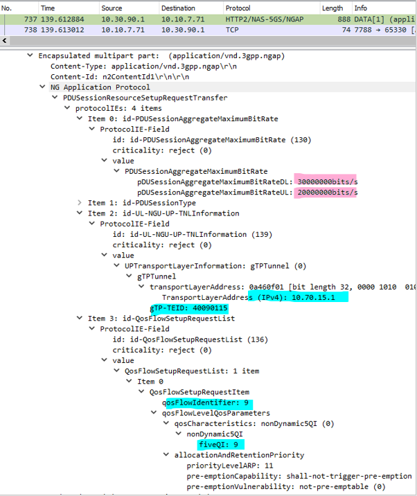
For the above N2 control plane message from the AMF to the gNB , the SMF advises the gNB (via the AMF) all the necessary QoS IEs for the UE’s PDU Session setup. This allows the gNB to make an independent QoS decision to establish the corresponding wireless transport to extend the CN_Tunnel of the UE’s N3 GTP-U tunnel to the gNB. The separation of QoS control between the access and the core networks enables the 5GC to support different wireless and wireline access networks and technology with very different QoS capabilities and characteristics.
The following summarizes the important IEs in the N2 message for the gNB:
- The IP address and the gTPTunnel (or CN_Tunnel) on the UPF is 10.70.15.1 and 40090115 respectively. This information is important for the gNB to forward the UE’s UL traffic to the DN via the UPF
- The same QFI = 9 is used for the gNB to identify the Default QoS Flow to be created for the UE’s PDU Session to the DN
- fiveQI or 5QI = 9 describes the QoS characteristic (e.g., best-effort non-GBR) of the Default QoS Flow of the UE’s PDU Session
- The UL and DL APN AMBRs (Aggregated Maximum Bit Rate) are 20Mbps and 30Mbps respectively
Frame 737 also contains the N1 control plane information for the UE described under the Non-Access-Stratum 5GS tag:
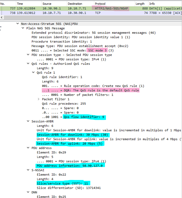
The following shows some key info included in the N1 control plane message for the UE:
- There is no Packet Filters for SDF binding as this is the Default QoS Flow
- The same QFI = 9 is used to identify the Default QoS Flow of the PDU Session for the UE
- UL and DL APN AMBRs are 20Mbps and 30Mbps respectively. The UE will enforce the UL non-GBR traffic to 20Mbps and drop any traffic over this limit
- The UE’s IP address is 50.90.127.0 and it is assigned by the SMF
The SST (Slice/Service Type) is 11, which is a reserved SST. The first four SSTs are standard and are defined as:
- 001 — eMBB (enhanced Mobile Broadband)
- 002 — URLLC (ultra-reliable low latency communication
- 003 — MIoT (Massive IoT)
- 004 — V2X (Vehicle to Vehicle communication)
The UE can now send its first UL packet to the DN because:
- The UE has the Default QoS Flow without any Packet Filter to match any UL traffic to the DRB (Data Radio Bearer) of the gNB using the QFI
- The gNB knows the IP address of the UPF and the TEID_cn of the UE’s PDU Session to forward its first UL packet to the DN via the UPF
D) 3GPP Messages 15 to 16 — PDU Session Setup for gNB and UPF (First DL Packet Ready)
While the UE can now send UL traffic to the DN via the gNB and the UPF, the UPF does not yet know the gNB’s IP address and the TEID_an for the UE’s PDU Session for sending DL traffic.
The 3GPP Message 15 shows the AMF’s Nsmf-PDU_Session_UpdateSMContext Request to the SMF to update the Session Management Context:

The AMF includes the following important IEs to the SMF so that the UPF can send the first DL packet to the UE via the gNB:
- The IP address of the gNB is 6.6.9.1 and the UE’s TEID_an (Access Node Tunnel Endpoint ID) is 0x100000001. Subsequently, on the 3GPP Message 16a, the SMF uses the N4 PCFP interface to advise the UPF about the gNB’s IP address and the UE’s TEID_an for the UPF to send the first DL packet to the UE via the gNB
- The same QFI = 9 is used to identify the default QoS Flow of the PDU Session of the UE
At this point, the UE’s PDU session to the DN is setup correctly and the UE and the DN can now use the Default QoS Flow with 5QI = 9 to exchange best-effort traffic or using the Default QoS Flow to signal a GBR Dedicated QoS Flow — See 5G Core Part 4 — Dedicated QoS Flow and PDU Session Modification for details.
Summary
This article describes in details how a UE can setup a PDU Session to a DN for traffic exchange under the 3GPP’s Procedures for the 5G System TS 23.502 Version 16.4.0. The semantics of the SBA SBI messages and their corresponding Wireshark capture are shown in this article.
You can follow me on www.medium.com for all my current and future articles on 5G Core, IP/MPLS and software technology.